SC-T7000 series/SC-T5000 series/SC-T3000 series Revision B
DISASSEMBLY & ASSEMBLY Disassembly and Assembly Procedure 96
Confidential
3.4.2.10 RIGHT LOWER COVER
1. Remove the UPPER LEFT COVER. (p100)
2. Remove the UPPER SUPPORT R COVER. (p94)
3. Remove the PANEL BOARD. (p120)
4. Remove the TOP COVER. (p85)
5. Remove the RIGHT UPPER COVER & RIGHT ROLL COVER. (p95)
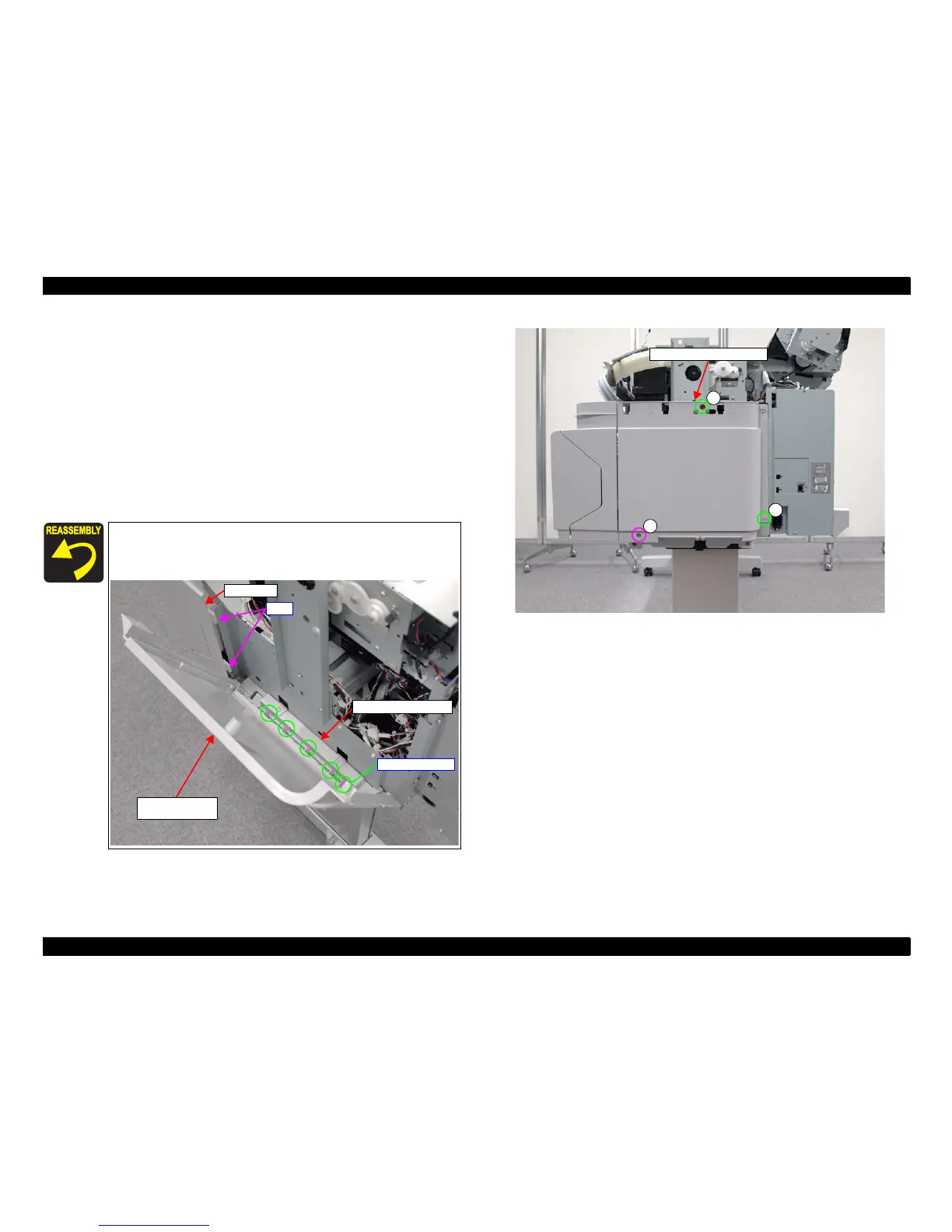
6. Remove the three screws, and remove the RIGHT LOWER COVER.
A) Silver M3x10 P-tite screw with washer: 1 pcs
B) Silver M3x8 S-tite screw with built-in washer: 2 pcs
Figure 3-23. Removing the RIGHT LOWER COVER
Insert the two tabs of the IH COVER to the two holes on the
RIGHT LOWER COVER.
Pay attention to the positioning points (See below figure).
RIGHT LOWER
COVER
IH COVER
RIGHT BASE COVER
Tabs
Positioning points
A
B
B
RIGHT LOWER COVER
 Loading...