SC-T7000 series/SC-T5000 series/SC-T3000 series Revision B
DISASSEMBLY & ASSEMBLY Disassembly and Assembly Procedure 111
Confidential
3.4.3 Electric Circuit Components
3.4.3.1 MAIN BOARD
1. Remove the UPPER LEFT COVER. (p100)
2. Remove the UPPER SUPPORT R COVER. (p94)
3. Remove the PANEL BOARD. (p120)
4. Remove the TOP COVER. (p85)
5. Remove the RIGHT UPPER COVER & RIGHT ROLL COVER. (p95)
6. Remove the REAR RIGHT LOWER COVER. (p99)
7. Remove the PSH BOARD. (p118)
8. Remove the MAIN-B BOARD. (p113)
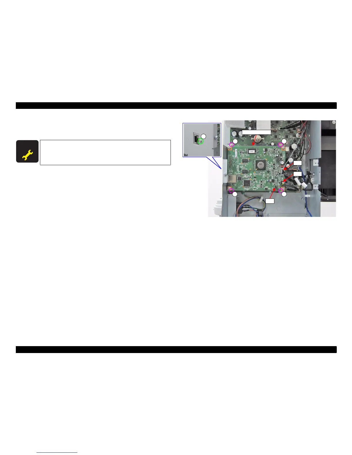
9. Disconnect the cables from the connectors (CN1, CN2, CN4) of the MAIN-C
BOARD.
10. Remove the five screws and remove the MAIN-C BOARD together with the
mounting plate.
A) Silver M3x6 screw: 4 pcs
B) Silver M2.5x6 Bind machine screw: 1 pcs
Figure 3-40. Removing the MAIN-C BOARD
A D J U S T M E N T
R E Q U I R E D
When replacing/removing this part, refer to “4.1.2 Adjustment
Items and the Order by Repaired Part” (p199) and make sure to
perform the specified operations including required adjustment.
B
MAIN-C BOARD
AA
A
CN1
CN2
CN4
A
 Loading...