SC-T7000 series/SC-T5000 series/SC-T3000 series Revision B
DISASSEMBLY & ASSEMBLY Disassembly and Assembly Procedure 159
Confidential
3.4.4.17 IM SENSOR
1. Perform the Tube inner pressure reduction. (p248)
2. Remove the UPPER LEFT COVER. (p100)
3. Remove the UPPER SUPPORT R COVER. (p94)
4. Remove the PANEL BOARD. (p120)
5. Remove the TOP COVER. (p85)
6. Remove the FRONT COVER. (p86)
7. Remove the LEFT UPPER COVER & LEFT ROLL COVER. (p101)
8. Remove the RIGHT UPPER COVER & RIGHT ROLL COVER. (p95)
9. Unlock the CR UNIT. (p83)
10. Remove the CR COVER. (p122)
11. Remove the DAMPER KIT. (p123)
12. Remove the PRINT HEAD. (p126)
13. Remove the RIGHT LOWER COVER. (p96)
14. Remove the APG UNIT. (p144)
15. Remove the CR MOTOR. (p141)
16. Remove the CR SCALE. (p135)
17. Remove the CR UNIT. (p156)
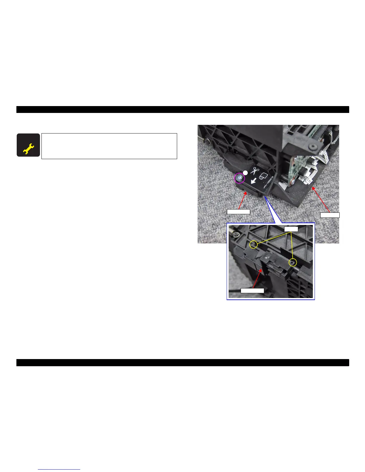
18. Remove the screw that secures the Sensor Cover.
A) Silver M3x8 P-tite screw with built-in washer: 1 pcs
19. Disengage the two hooks, and remove the Sensor Cover.
Figure 3-111. Removing the Sensor Cover
A D J U S T M E N T
R E Q U I R E D
When replacing/removing this part, refer to “4.1.2 Adjustment
Items and the Order by Repaired Part” (p199) and make sure to
perform the specified operations including required adjustment.
Hooks
Sensor Cover
Sensor Cover
A
CR UNIT
 Loading...