SC-T7000 series/SC-T5000 series/SC-T3000 series Revision B
DISASSEMBLY & ASSEMBLY Disassembly and Assembly Procedure 148
Confidential
3.4.4.14 IC HOLDER
1. Perform the Ink eject. (p259)
2. Perform the Tube inner pressure reduction. (p248)
3. Remove the UPPER LEFT COVER. (p100)
4. Remove the UPPER SUPPORT R COVER. (p94)
5. Remove the PANEL BOARD. (p120)
6. Remove the TOP COVER. (p85)
7. Remove the RIGHT UPPER COVER & RIGHT ROLL COVER. (p95)
8. Remove the FRONT COVER. (p86)
9. Remove the RIGHT LOWER COVER. (p96)
10. Remove the IH COVER. (p89)
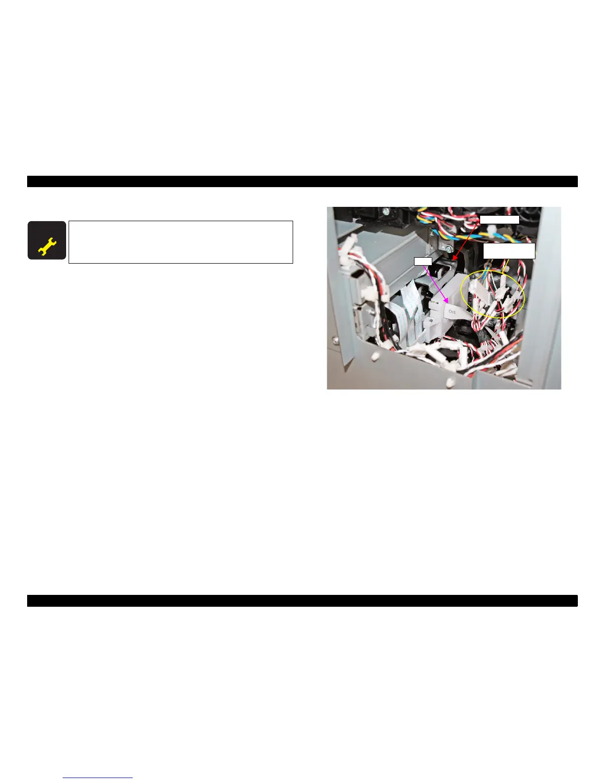
11. Disconnect the cable from the Relay Connector (No.2, No.8, No.10).
12. Remove the FFC from the back side of the IC HOLDER.
Figure 3-96. Disconnecting the Relay connectors and FFC
A D J U S T M E N T
R E Q U I R E D
When replacing/removing this part, refer to “4.1.2 Adjustment
Items and the Order by Repaired Part” (p199) and make sure to
perform the specified operations including required adjustment.
Relay Connector
(No.2, No.8, No.10)
FFC
IC HOLDER
 Loading...