SC-T7000 series/SC-T5000 series/SC-T3000 series Revision B
DISASSEMBLY & ASSEMBLY Disassembly and Assembly Procedure 147
Confidential
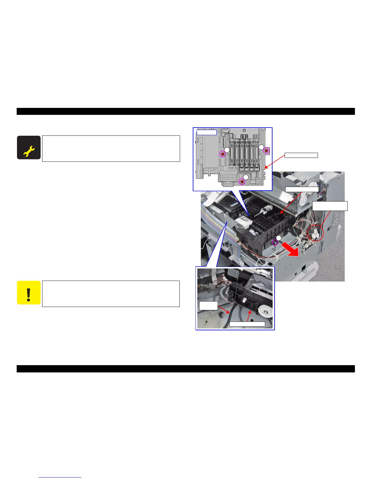
3.4.4.13 PUMP CAP UNIT
1. Remove the UPPER LEFT COVER. (p100)
2. Remove the UPPER SUPPORT R COVER. (p94)
3. Remove the PANEL BOARD. (p120)
4. Remove the TOP COVER. (p85)
5. Remove the RIGHT UPPER COVER & RIGHT ROLL COVER. (p95)
6. Remove the REAR RIGHT LOWER COVER. (p99)
7. Remove the RIGHT LOWER COVER. (p96)
8. Unlock the CR UNIT.(p83)
9. Move the CR UNIT on the Platen.
10. Remove the R Reinforce Plate. (p144)
11. Disconnect the cables from the Relay Connector (No.7, No.11, No.34).
12. Remove the three screws that secure the PUMP CAP UNIT.
A) Silver M3x8 S-tite screw with built-in washer: 3 pcs
13. Remove the Waste Ink Tube from the PUMP CAP UNIT.
14. Remove the PUMP CAP UNIT in the direction of the arrow.
Figure 3-95. Removing the PUMP CAP UNIT
A D J U S T M E N T
R E Q U I R E D
When replacing/removing this part, refer to “4.1.2 Adjustment
Items and the Order by Repaired Part” (p199) and make sure to
perform the specified operations including required adjustment.
C A U T I O N
In the next step, waste ink may spill from the Waste Ink Tube if the
tube is disconnected from the PUMP CAP UNIT. Prepare a waste
cloth or the like in advance and be careful not to contaminate the
surroundings.
Relay Connector
(No.7, No.11, No.34)
A
A
A
Upper side
PUMP CAP UNIT
A
Waste Ink
Tube
PUMP CAP UNIT
PUMP CAP UNIT
 Loading...