SC-T7000 series/SC-T5000 series/SC-T3000 series Revision B
DISASSEMBLY & ASSEMBLY Disassembly and Assembly Procedure 181
Confidential
3.4.6 Cutter Mechanism
3.4.6.1 CUTTER UNIT
1. Remove the UPPER LEFT COVER. (p100)
2. Remove the UPPER SUPPORT R COVER. (p94)
3. Remove the FRONT COVER. (p86)
4. Remove the TOP COVER. (p85)
5. Remove the RIGHT UPPER COVER & RIGHT ROLL COVER. (p95)
6. Remove the FRONT COVER. (p86)
7. Remove the LEFT UPPER COVER & LEFT ROLL COVER. (p101)
8. Remove the LEFT LOWER COVER. (p98)
9. Remove the RIGHT LOWER COVER. (p96)
10. Remove the FRONT LEFT LOWER COVER. (p103)
11. Remove the IH COVER. (p89)
12. Remove the LOWER PAPER GUIDE B. (p88)
13. Remove the LOWER PAPER GUIDE. (p87)
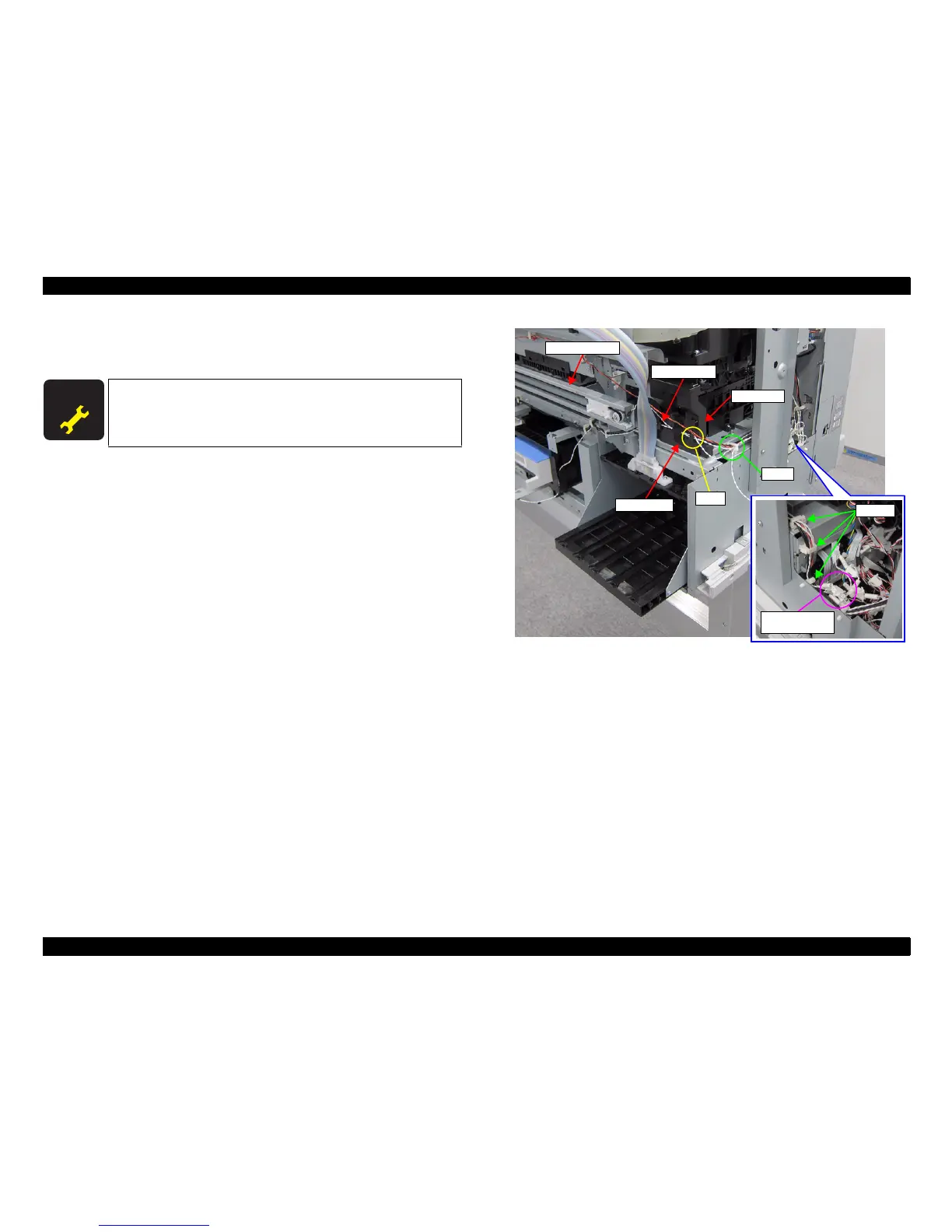
14. Disconnect the sensor cable from the Relay Connector (No.27).
15. Release the sensor cable from the four clamps.
16. Remove the pieces of acetate tape, and release the sensor cable.
17. Release the sensor cable from the hook of the CR Spacer.
Figure 3-143. Releasing the Sensor Cable
A D J U S T M E N T
R E Q U I R E D
When replacing/removing this part, refer to “4.1.2 Adjustment
Items and the Order by Repaired Part” (p199) and make sure to
perform the specified operations including required adjustment.
Sensor cable
CUTTER UNIT
CR Spacer
Clamps
Relay Connector
(No.27)
Acetate tape
Clamp
Hook
 Loading...