SC-T7000 series/SC-T5000 series/SC-T3000 series Revision B
DISASSEMBLY & ASSEMBLY Disassembly and Assembly Procedure 173
Confidential
3.4.5.7 PRESSURE ROLLER SENSOR
1. Remove the UPPER LEFT COVER. (p100)
2. Remove the UPPER SUPPORT R COVER. (p94)
3. Remove the PANEL BOARD. (p120)
4. Remove the TOP COVER. (p85)
5. Remove the FRONT COVER. (p86)
6. Remove the LEFT UPPER COVER & LEFT ROLL COVER. (p101)
7. Remove the REAR LEFT LOWER COVER. (p104)
8. Remove the LEFT LOWER COVER. (p98)
9. Remove the PF MOTOR. (p163)
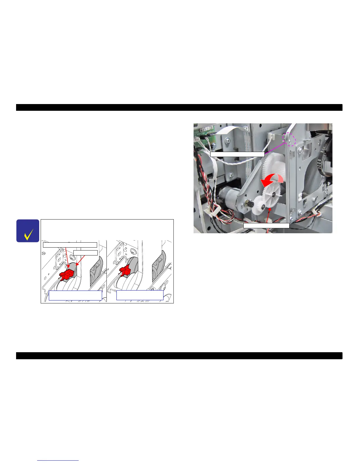
10. Rotate the Combination gear 18.4, 37.6 counterclockwise to set the PRESSURE
ROLLER in the release position (The sensor is in the transmissive state.).
Figure 3-129. Rotate the Combination gear 18.4, 37.6
C H E C K
P O I N T
Confirm the status of the PRESSURE ROLLER with the relative
positions of the PRESSURE ROLLER SENSOR and Spur Gear 43
as shown below.
PRESSURE ROLLER SENSOR
PRESSURE ROLLER: Release
Sensor: Transmissive
Spur Gear 43
PRESSURE ROLLER: Nip
Sensor: Shaded
Combination gear 18.4, 37.6
PRESSURE ROLLER SENSOR
 Loading...