SC-T7000 series/SC-T5000 series/SC-T3000 series Revision B
DISASSEMBLY & ASSEMBLY Disassembly and Assembly Procedure 105
Confidential
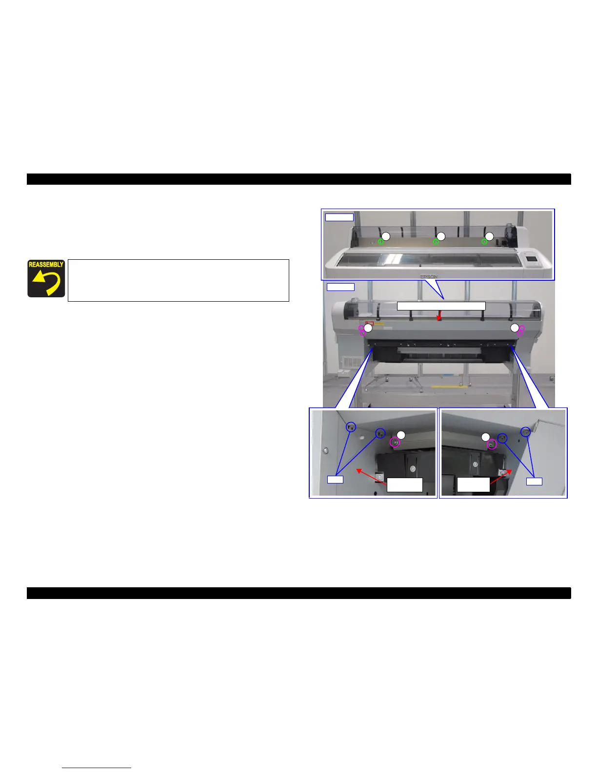
3.4.2.19 REAR ROLL COVER FRAME
1. Remove the nine screws, and remove the REAR ROLL COVER FRAME.
A) Silver M4x8 S-tite screw with built-in washer: 6 pcs
B) Silver M3x8 P-tite screw with built-in washer: 3 pcs
Figure 3-32. Removing the REAR ROLL COVER FRAME
Place the REAR ROLL COVER FRAME so that it will come on all
the four tabs of the R Side Roll Frame and L Side Roll Frame.
Front side
B
BB
A
Tabs
L Side Roll
Frame
A
R Side Roll
Frame
Tabs
Back side
A
REAR ROLL COVER FRAME
A
 Loading...