SC-T7000 series/SC-T5000 series/SC-T3000 series Revision B
DISASSEMBLY & ASSEMBLY Disassembly and Assembly Procedure 156
Confidential
3.4.4.16 CR UNIT
1. Perform the Tube inner pressure reduction. (p248)
2. Remove the UPPER LEFT COVER. (p100)
3. Remove the UPPER SUPPORT R COVER. (p94)
4. Remove the PANEL BOARD. (p120)
5. Remove the TOP COVER. (p85)
6. Remove the FRONT COVER. (p86)
7. Remove the LEFT UPPER COVER & LEFT ROLL COVER. (p101)
8. Remove the RIGHT UPPER COVER & RIGHT ROLL COVER. (p95)
9. Unlock the CR UNIT. (p83)
10. Remove the CR COVER. (p122)
11. Remove the DAMPER KIT. (p123)
12. Remove the PRINT HEAD. (p126)
13. Remove the RIGHT LOWER COVER. (p96)
14. Remove the APG UNIT. (p144)
15. Remove the CR MOTOR. (p141)
16. Remove the CR SCALE. (p135)
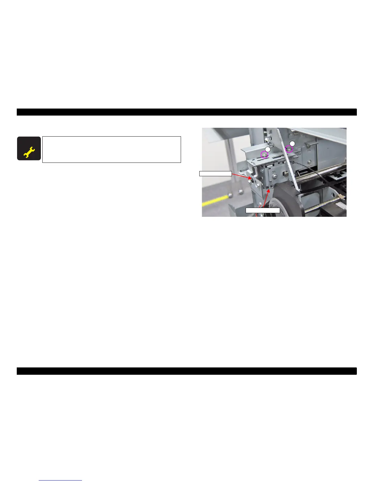
17. Remove the Belt tension screw and the two screws on the upper part of the Pulley
Holder Assy, then remove the Pulley Holder Assy.
A) Silver M3x6 S-tite screw with built-in washer: 2 pcs
Figure 3-106. Removing the Pulley Holder Assy
A D J U S T M E N T
R E Q U I R E D
When replacing/removing this part, refer to “4.1.2 Adjustment
Items and the Order by Repaired Part” (p199) and make sure to
perform the specified operations including required adjustment.
Pulley Holder Assy
A
A
Belt tension screw
 Loading...