SC-T7000 series/SC-T5000 series/SC-T3000 series Revision B
DISASSEMBLY & ASSEMBLY Disassembly and Assembly Procedure 171
Confidential
3.4.5.6 PRESSURE ROLLER MOTOR
1. Remove the UPPER LEFT COVER. (p100)
2. Remove the UPPER SUPPORT R COVER. (p94)
3. Remove the PANEL BOARD. (p120)
4. Remove the TOP COVER. (p85)
5. Remove the FRONT COVER. (p86)
6. Remove the LEFT UPPER COVER & LEFT ROLL COVER. (p101)
7. Remove the REAR LEFT LOWER COVER. (p104)
8. Remove the LEFT LOWER COVER. (p98)
9. Remove the Rear Cover Cap while sliding in the direction of the arrow.
Figure 3-126. Removing the Rear Cover Cup
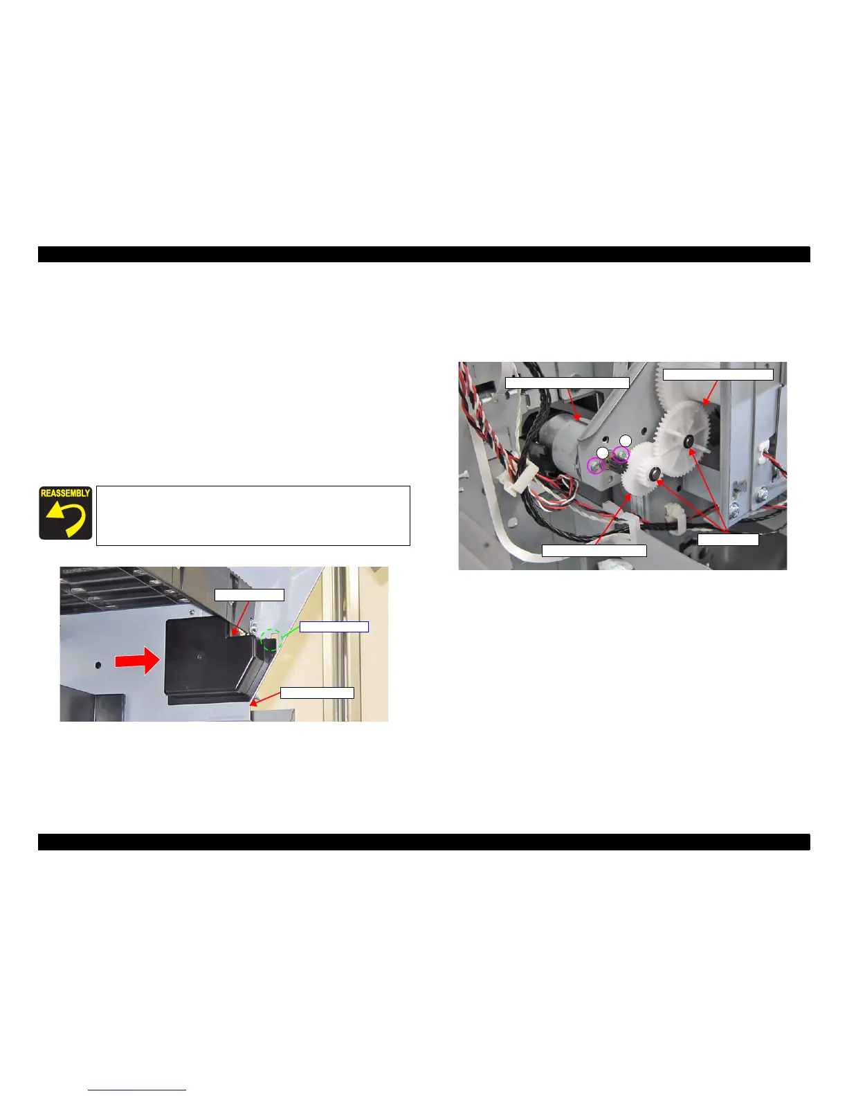
10. Remove the two Plastic washers, and remove the Combination gear 26, 12.8 and
Combination gear 18.4, 37.6.
11. Remove the two screws, and remove the PRESSURE ROLLER MOTOR.
A) Silver M2.6x4 machine screw: 2 pcs
Figure 3-127. Removing the Combination gear 26, 12.8 and Combination gear 18.4, 37.6
Pay attention to the positioning point (See Figure 3-126).
Rear Cover Cap
L Roll Side Frame
Positioning point
PRESSURE ROLLER MOTOR
A
A
Combination gear 18.4, 37.6
Combination gear 26, 12.8
Plastic washers
 Loading...