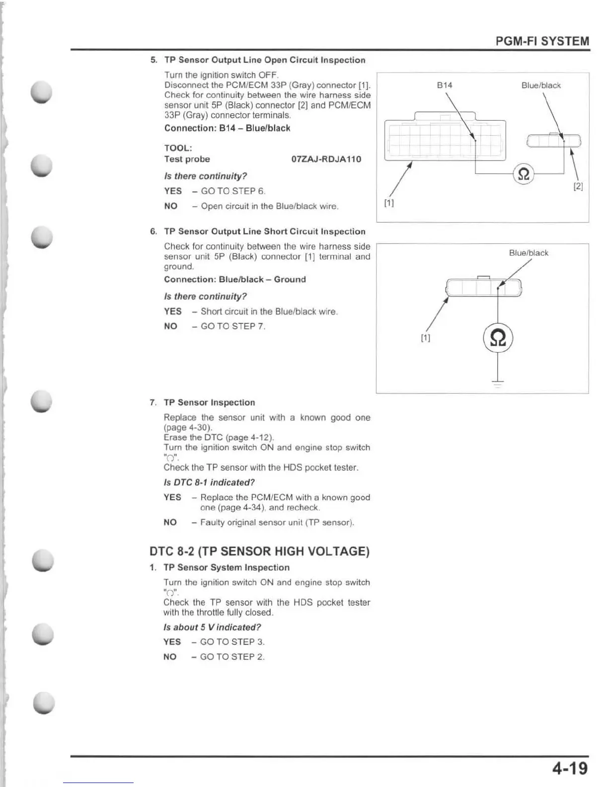
5.
TP
Sensor
Output
Line Open Ci r
cuit
Insp
ec
tion
Turn the ignition switch OFF.
Disconnect the
PCM
/
ECM
33P (Gray) connector [1].
Check for continuity between the wire harness side
sensor unit 5P (Black) connector [2) and PCM/ECM
33P (Gray) connector terminals.
Connection:
814
- Blue/black
TOOL:
Test
probe
07ZAJ·RDJA1 10
Is there
continuity
?
YES -
GO
TO
STEP
6.
NO -
Open
circuit in t
he
Blue/black wire.
6. TP
Sensor
Output
Lin
e
Short
Cir
c
uit
Inspection
Check for continuity between the wire harness si de
,--
sensor unit 5P (Black) connector
[1}
terminal and
ground.
Connection
: Blue/
black
-
Ground
Is
there continuity?
YES - Short circuil
in
the Bluelblack wire.
NO -
GO
TO
STEP
7.
7. TP
Sensor
Inspec
ti
on
Replace the sensor unit with a known
good
one
(page 4·30).
Erase the OTC (page 4.12).
Tum the ignition switch ON and engine stop switch
wOw.
Check the T P sensor with the HOS pocket tester.
Is OTC
B·1
indicated?
YES - Replace the
PC
M/ECM with a known good
one (page
4·34), and recheck.
NO - Faulty original sensor unit (TP sensor).
DTC 8·2 (TP SENSOR HIGH VOLTAGE)
1. TP
Sensor
System
Inspection
Tum the ignition switch ON and engine stop switch
·0
·,
Check the TP sensor with the HOS pocket tester
with
Ihe Ihrottle
fuUy
closed.
Is a
bout
5 V
indicated
?
YES - GO TO ST EP
3.
NO - GO TO STEP 2.
PGM·FI SYSTEM
.,4
Blue/blacKI
(11
4·19

 Loading...