POWER/GROUND LINE INSPECTION
Disconnect
the
combination
meier
21
P
connec
t
or
(page
22-6),
Check the power and ground lines at the wi
re
harness
side connector.
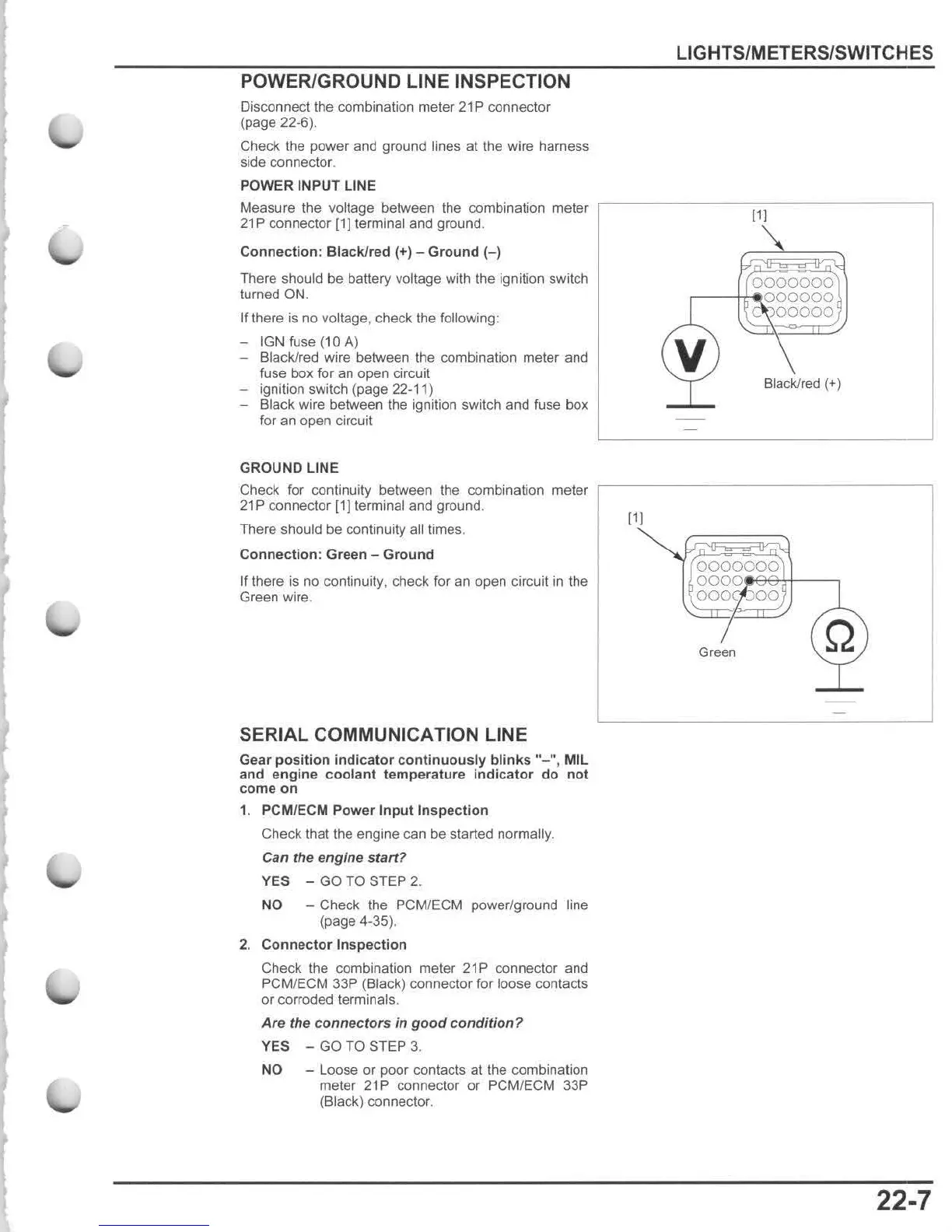
POWER
INPUT
LINE
Measure
the
voltage between
the
combination meter
21
P connector [1] terminal
and
ground
.
Connection
: Black/red (+) -
Ground
(-)
There
should be battery voltage with the ignition switch
turned ON.
If
there is no voltage,
check
Ihe
following:
- IGN fuse ( 10
A)
- Black/red wire between the combination meter and
fuse
box
for
an
open
circuit
- ignition switch
(page
22-11)
-
Black
wire
between the ignition switch and fuse
box
for an open circuit
GROUND
LINE
Check for continuity between the combination meter
21P
connector
[11
terminal
and
ground.
There should
be
continuity all times.
Connection
: Green -
Ground
If there
is
no continuity, check for an open circuit in the
Green wire.
SERIAL
COMMUNICATION LINE
Gear
position
indicator
continuously
blinks
"
-",
MIL
and
engine
coolant
temperature
indicator
do
not
come
on
1. PCMIECM
Power
Input
Inspection
Check that the engine can be started normally.
Can the engine s
taff
?
YES
-
GO
TO
STEP
2.
NO
- Check the PCM/ECM power/ground line
(page 4-35).
2.
Connector
Inspection
Check the combination meter
21
P connector and
PCM/ECM 33P (Black) connector for loose contacts
or
corroded terminals.
Are the connectors in
good
condition?
YES
-
GO
TO
STEP
3.
NO
- Loose or poor contacts at the combination
meter 21P connector
or
PCMIECM 33P
(Black) connector.
[1
[
LIGHTS/METERS/SWITCHES
[1
[
0000000
,--tt"!
OOOOOO
CJOOOOO
v
Black/red (+)
0000000
OOOO'
fteetf------,
000(:)00
Green
22-7

 Loading...