ELECTRIC POWER STEERING (EPS : FPMfFPE
models)
24·24
DTC 18-03: EPS ECU INTERNAL
CIRCUIT
(CURRENT SENSOR STUCK
LOW) (INITIAL DIAGNOSIS)
NOTE :
Before starting the troubleshooting, check for loose
or
poor contact
of
the following connectors, and recheck
the DTG (page 24-18).
-
EPS ECU 2P (Gray)
- EPS motor
2P
(Gray)
1.
EP$
ECU
System
Inspection
1. Erase the
DIC
(page 24-11).
2.
Start the engine.
3. Fully tum
the
handlebar
to
the
left or right
and
hold
il10
seconds.
4.
Check the EPS indicator.
Does the
EP$
Indicator come on?
YES -
GO
TO
STEP
2.
NO
- Intermittent failure.
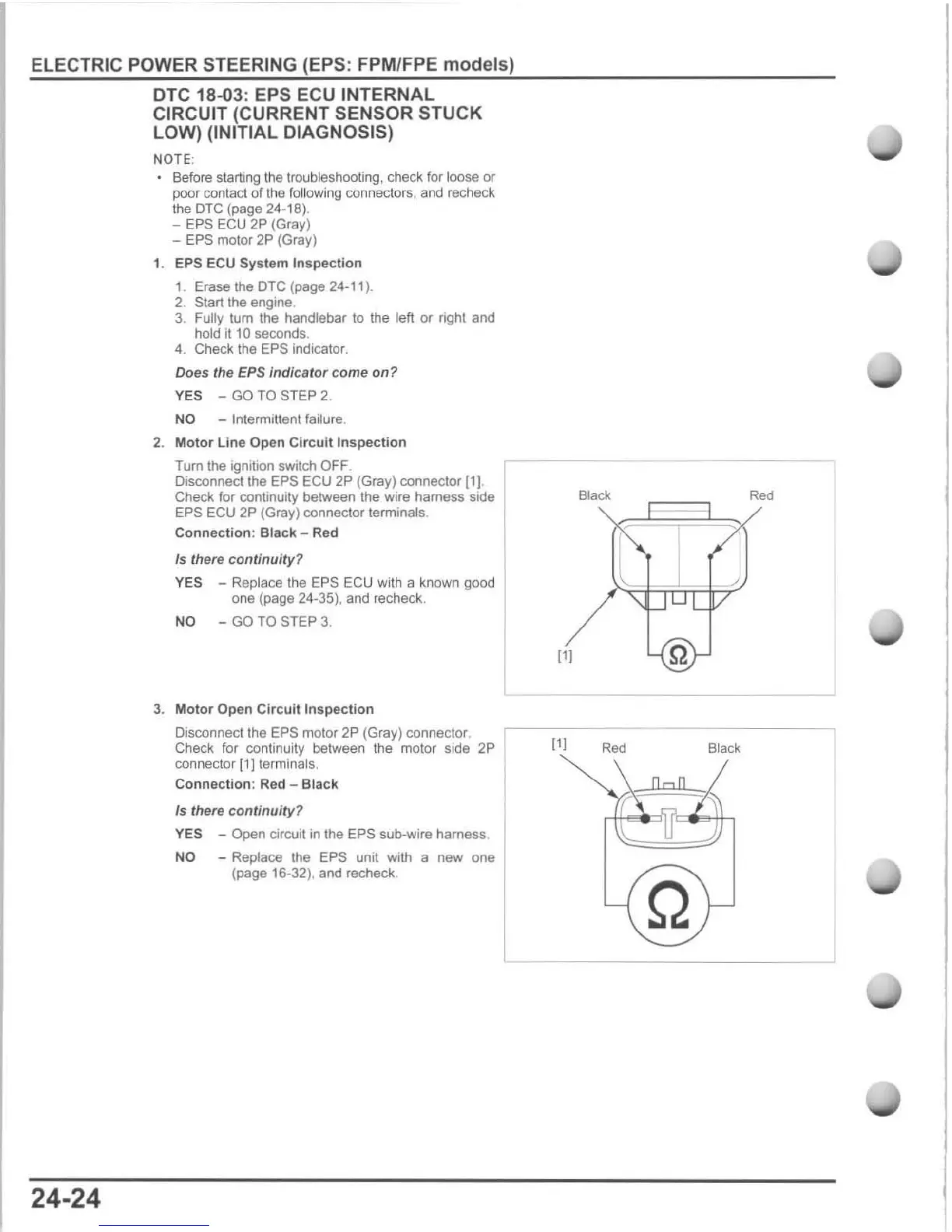
2.
Motor
Line
Open
Circuit
Inspection
Turn the ignition switch
OFF
.
Disconnect the EPS
EGU
2P
(Gray) connector
Ill
.
Check for continUIty between the wire harness side
EPS EGU 2P (Gray) connector terminals.
Connection
: Black - Red
Is
there
continuity?
YES - Replace the EPS ECU with a known good
one (page 24-35),
and
recheck.
NO
-
GO
TO
STEP
3.
3.
Motor Open Circuit Inspection
Oisconnecllhe
EPS
motor
2P
(Gray) connector, I
Check for continuity between the motor side 2P
connector
[1)
terminals,
Connection:
Red
- Black
Is
there
continuity
?
YES
- Open circuit in the
EPS
sub-wire harness
NO
- Replace the EPS unit with a new one
(page 16-32), and recheck.
I
I
[11
~
111
Red
Black
Q

 Loading...