ELECTRIC POWER STEERING (EPS: FPM/FPE
models)
DTC
TROUBLESHOOTING
24-18
NOTE '
Refer
to
"EPS Connector Location" for the connector
location and
the
necessary parts to disconnect the
connector (page 24-5),
After troubleshooting, erase t
he
o TC(s) and test-ri
de
the
vehicle
to
be
su
re that the EPS indicator does
not come
on.
VERIFY PROPER CONNECTOR
CONTACT
Many EPS problems and subsequent oTCs are caused
by poor connector contacts. The first step
in
troubleshooting
any
DTC is to inspect the affected
connectors.
CONNECTOR INSPECTION
Check for moisture
In
the affected connector
Check for corrosion
Check for
folded pins
on
the male side
of
the
connector
Check for
loose pins andl
or
pins pushed out
of
the
connector
DTC
11·01 : EXCESSIVE CHANGE
OF
VEHICLE SPEED SIGNAL (REGULAR
DIAGNOSIS)
NOTE:
Before starting
the
troubleshooting, check for loose
or
poor contact of the following connectors, and recheck
the
EPS indicator (page 24-1
8).
- engine sub-wire harness connector
-
3P
(Black): FPM
- 6P (Black
):
FPE
-
EPS ECU 21P (Gray)
-
VS
sensor
3P
(Black)
The
system is reducing the assist power, the EPS
indicator will come
on
when t
he
EP
S ECU detects
conditions
of
orc
11·01 and
OTC
11-02.
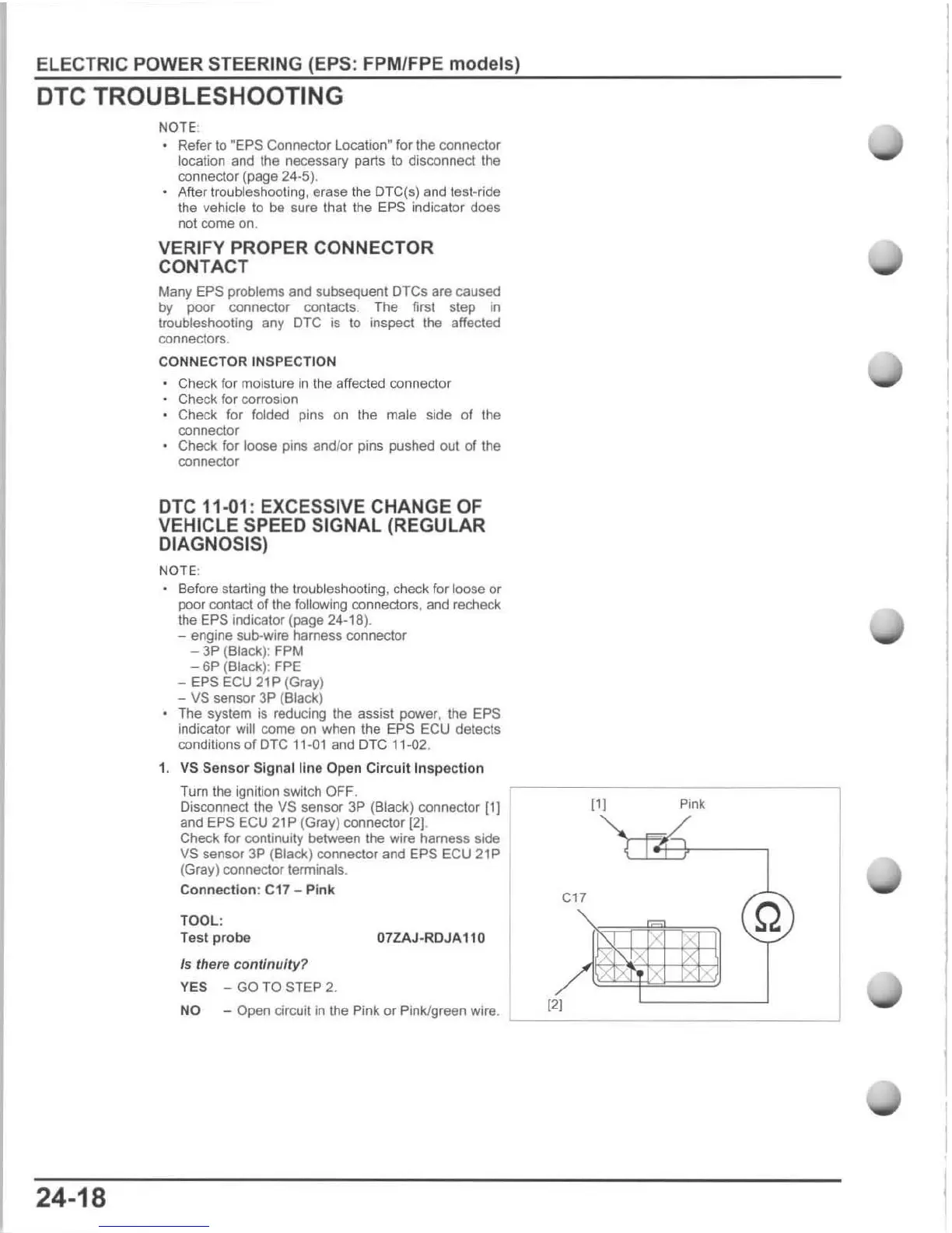
1. VS Sensor Signal line Open
Circuit
Inspe
ction
Turn
the
ignition switch OFF.
Disconnect the VS sensor 3P (Black) connector
[1]
and EPS ECU 21P
(G
ray) connector
[2J
.
Check for continuity between
the
wire harness side
VS sensor
3P
(Black) connector and EPS ECU 21P
(Gray)
con
nector terminals,
Connection
: C17 - Pi nk
TOOL:
Test
probe
07ZAJ-RDJA110
Is there continuity?
YES -
GO
TO STEP 2.
NO - Open circuit
in
the Pink or Pink/green wire.
[l [
Pink
ell
Q
x
x
[2[

 Loading...