Align the edge
of
the master cylinder
with the punch
mark
{51
on the
handlebar.
Connect the gray
Jape
(4J
wire
connectors
10
th
e
u
pper
terminals.
BRAKE SYSTEM
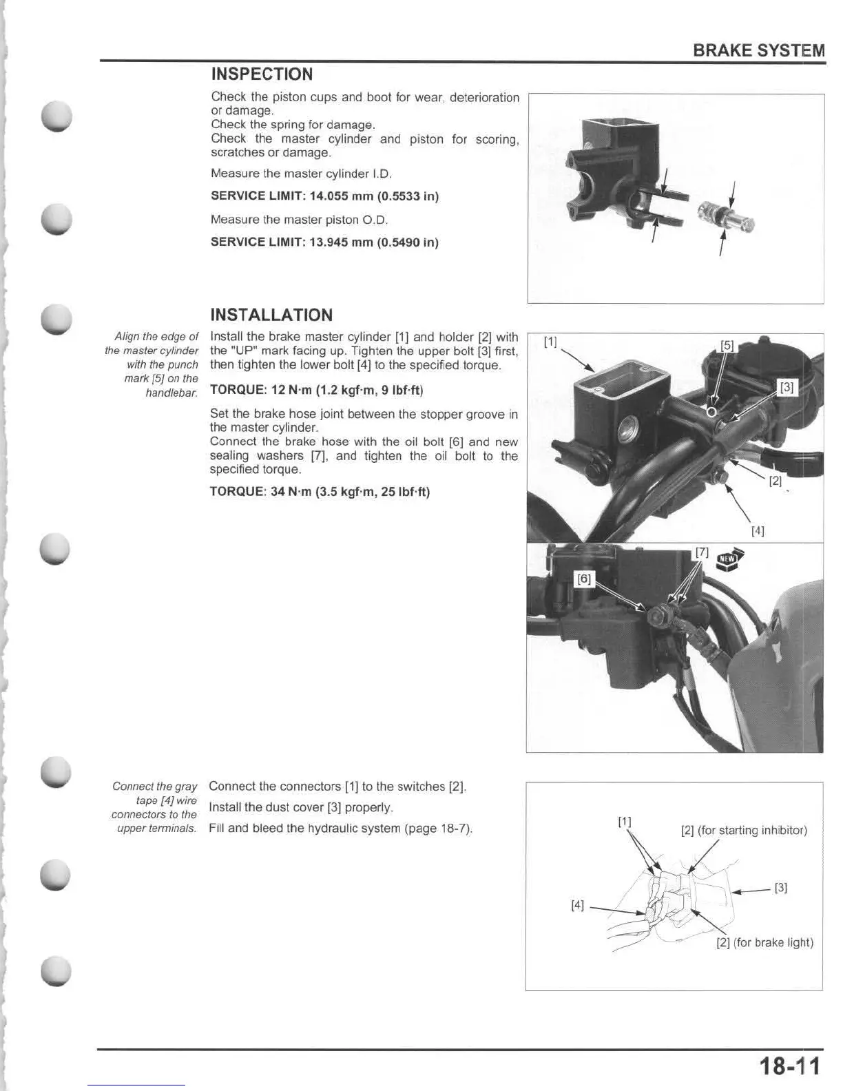
INSPECTION
Check the piston cups and boot for wear, deterioration
,---------
-
-----
-
-----,
or damage.
Check the spring for damage.
Check the master cylinder and piston for scoring.
scratches
or
damage.
Measure the master
cylinder 1.0.
SERVICE LIMIT: 14.055
mm
(0.5533 in)
Measure the master piston O.
D.
SERVICE LIMIT: 13.945
mm
(0.5490 in)
INSTALLATION
Instalilhe
brake master cylinder [1] and holder [2] with
~
=------------
__.._
--
,
the "UP· mark facing up. Tighten the upper bolt
f3J
first,
then lighten the lower bolt [4] to the speCified torque.
TORQUE: 12 N'm (1.2
kgf
-m, 9
IbUt)
Set the brake hose joint between the stopper groove
in
the master cylinder.
Connect the brake hose with the oil bolt [6] and new
sealing washers
(7]
. and tighten the oil bolt
to
the
specified torque,
TORQUE: 34
N'm (3.5
kgf
'm , 25 Ibf-ft)
Connect
the connectors [1] to the switches [2].
Insta!1
the dust cover {3] properly.
Fill
and bleed the hydraulic system (page 18-7).
(1(
[21
(for starting inhibitor)
I-
_
131
(4(
~?!I
J;;"
~
(21
(for brake light)
18-11

 Loading...