PGM-FI SYSTEM
3.
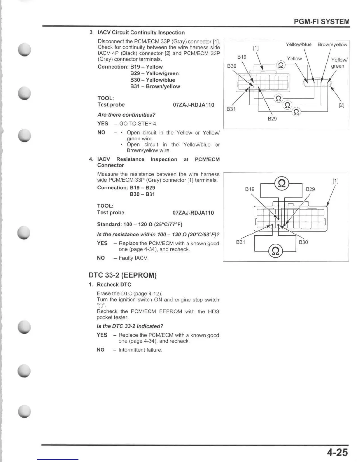
IACV
Circuit
Continuity
Inspection
Disconnect the
PCM/
E
CM
33P (Gray) connector
[1).
'-----
---
~Y~e~II-0w-l~b~,"-e-B=,
-o-
w
-
o
~l
y
-
e
~
1I0
-w
'
Check for continuity between the wire harness side
[1J
IACV 4P (Black) connector
[21
and PCMIECM 33P
(Gray) connector terminals.
Connection
: 819 -
Yellow
829
-
Yellow
/
green
B30 -
Yellow
/
blue
831 -
Brown
/
yellow
TOOL:
Test
probe
07ZAJ·RDJA110
Are there continuities ?
YES - GO TO STEP
4.
NO Open circuil
in
the Yellow or Yellowl
green
wi
r
e.
Open circuit
in
the Yellow/blue or
Brown/yellow wire.
4.
IACV Resistance
Inspection
at PCM/ECM
Connector
Measure the resistance between the wire harness
side
PCM/ECM 33P (Gray) connector
[1]lerminals
.
Connection:
819
-
829
B30 - 831
TOOL:
Test
probe
07ZAJ·RDJA110
Standard: 100
-120
0 (25
G
Cf7rF)
Is
the
res/stance
within
100 - 120
{J
(20GC/68
G
F
)?
YES - Replace the PCM/ECM with a known good
one (page 4-34), and recheck.
NO
- Faulty IACV.
OTe 33-2 (EEPROM)
1.
Recheck
orc
Erase the DTC (page 4-12).
Turn the ignition switch
ON and engine stop switch
~OH.
Recheck the PCM/ECM EEPROM with the HDS
pocket tester.
Is
the
DTe
33-2
indicated
?
YES - Replace the PCM/ECM with a known good
one (page 4-34), and recheck.
NO
-
In
termittent failure.
B19
Yellow Yellow!
B30
~ti
q
~
gleeo
~
B31
B31
'+\,~-{
Q
l-=-
-
---'
~
:
=_----l
'-----'\--=-{
:Q
)-
- ---'
B29
B19 B29
B30
[2[
[11
4-25

 Loading...