PGM·FI SYSTEM
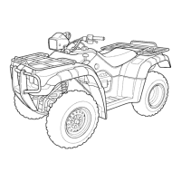
Connect
an
ohmmeter
to
the fuel pump relay side 8P
connector
[1J
te
r
minals
as shown.
Connection
: A - B
Connect the 12 V battery
[21
to
the fuel
pump
relay side
8P
connector terminals
as
shown.
Connection: E - F
There should be continuity with the ba
tt
ery connected
and no continuity with the
bat
tery disconnected.
If the test result is abnormal. replace the fuel pump
relay.
SENSOR UNIT (MAP/TP SENSOR)
REMOVAL/INSTALLATION
4·30
NOTE:
If
the sensor unit has been removed , perform the
TP
sensor reset procedure
(page
4~3
1 )
.
Always clean around the throttle body before the
sensor unit removal
to
prevent di
rt
and debris from
entering the air passage.
Remove the following:
- throttle body
cover
(page 7-13)
- left side
cover
(page 2-4)
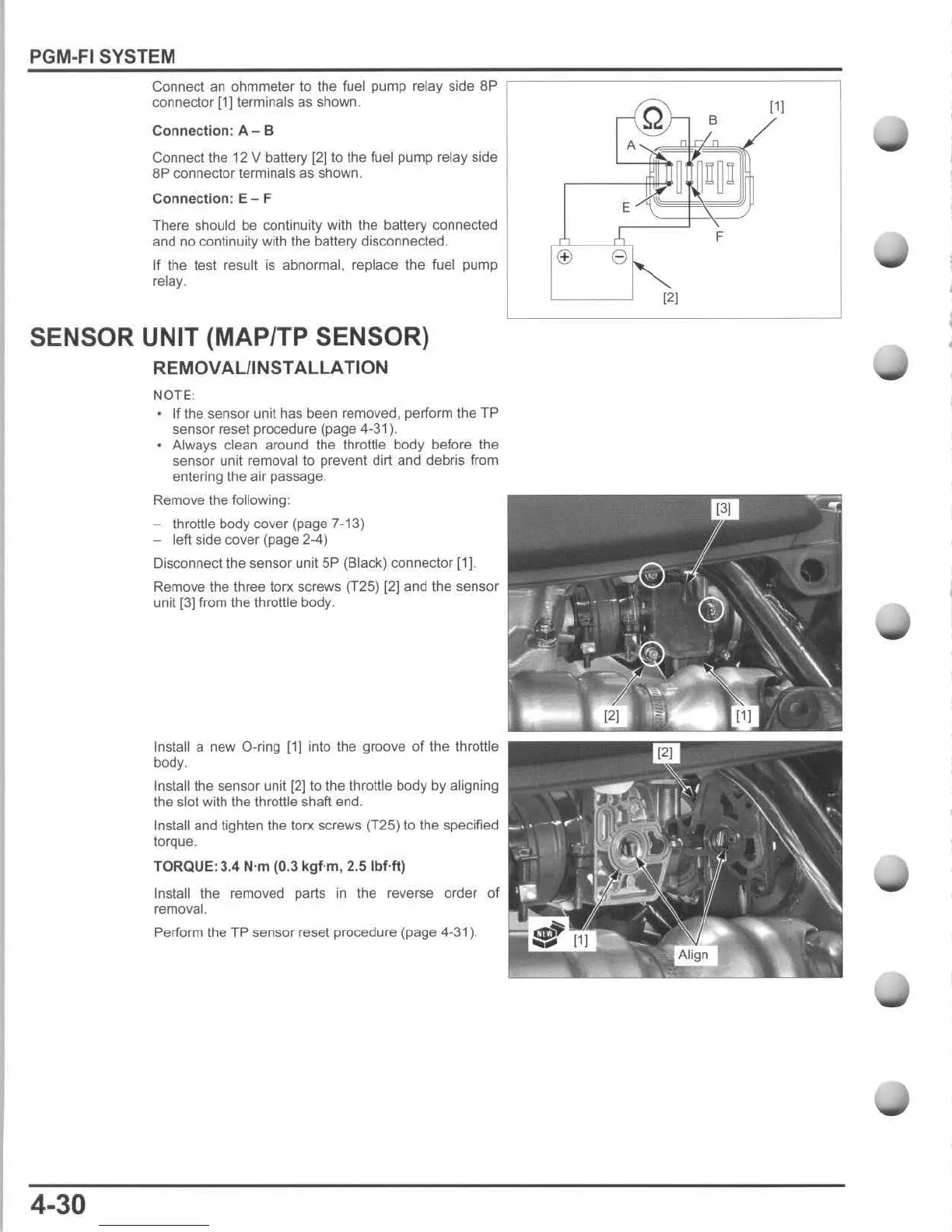
Disconnect the sensor unit
SP
(Black) connector [1].
Remove the three torx screws (T2S)
{2]
and the sensor
unit
[3} from the throttle body.
Install a new O-ring
[1]
into the groove
of
the throttle
body.
Instalilhe sensor unit [2]
to
the throttle body by aligning
the slot with the throttle sha
ft
end.
Install and tighten the torx screws (T2S) to the specified
torque.
TORQUE:
3.4 N·m
(O
.3
kgf
·m , 2.5
IbHt)
Install the removed parts
in
the reverse order of
removal.
Perform
the TP sensor reset procedure (page 4-31).
r-®-:
B
11)
A .j ,
~
~.~
E.A
F
<±>
8
Ii,)

 Loading...