LIGHTS/METERS/SWITCHES
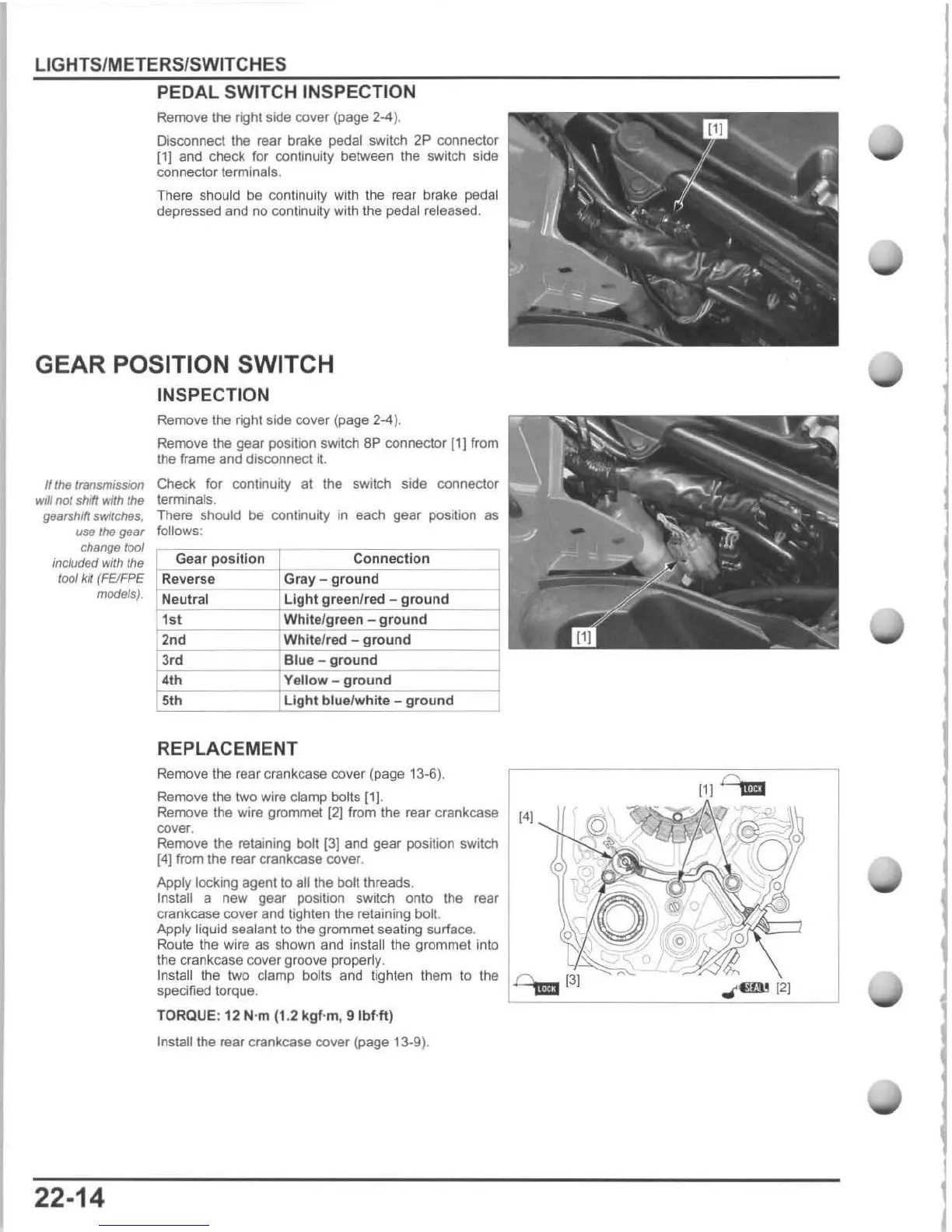
PEDAL SWITCH INSPECTION
Remove the right side
cover
(page
2-4)
.
Disconnect the
rear
brake
pedal switch
2P
connector
!11
and
check for continuity between
the
switch side
connector terminals.
There should be continuity with the rBar brake pedal
depressed and no continuity with the pedal released.
GEAR POSITION SWITCH
INSPECTION
If
the
tranSlntsslO/1
wJii
not shift with tho
gearshift
switches,
use
the
gear
change
tool
included with the
tool kit
(FElFPE
models),
22-14
Remove the right side
cover
(page 2-4).
Remove the
gear
position switch BP connector [1]
from
the frame and disconnect
it.
Check for continuity at the switch side connector
terminals.
There should be continuity
in
each gear position as
follows:
G
ea
r po
si
tion Connection
Reverse Gray -
gr
o
und
~
N
"e::
"
"
I
=
"
~
I
~~~~~~!~
L
",I!!c
9
~
hl
:,
9
~
,
.::
.=.fj
n
jf:.:
,
::e:.:
d
"
,--
-::
9
;;
'
-=
o
:-
~
"
-:-
::
n
::
d
~
----1
1s t W
hi
t
e/
gr
ee
n -
gr
ound
2n
d Whit
e/
red -
gr
ound
3r
d Blue - g
round
4th Yellow -
ground
5th Light
blu
elw
hit
e - ground
REPLACEMENT
Remove the rear crankcase cover (page 13-6).
Remove the
two
wire clamp bolts
111
.
Remove the wire grommet
(21
from the rear crankcase
[4)
cover.
Remove the retaining
bolt
(31
and
gear position switch
[4]
from the rear crankcase cover.
Apply
locking agent to all the bolt threads.
Install a new gear position switch onto the rear
crankcase cover and tighten the retaining bolt.
Apply liquid sealant to
the
grommet seating surface.
Route the wire
as
shown
and
install the grommet into
the crankcase cover groove properly.
Install the two clamp bolts
and
tighten them
to
the
specified torque.
TORQUE :
12 N·m (1.2 kgf·m,
9lbHt
)
Install
the rear crankcase cover (page 13-9).
111
0,.
o
.,(1lW
121
I
I

 Loading...