ELECTRIC SHIFT PROGRAM (ESP: FE/FPE models)
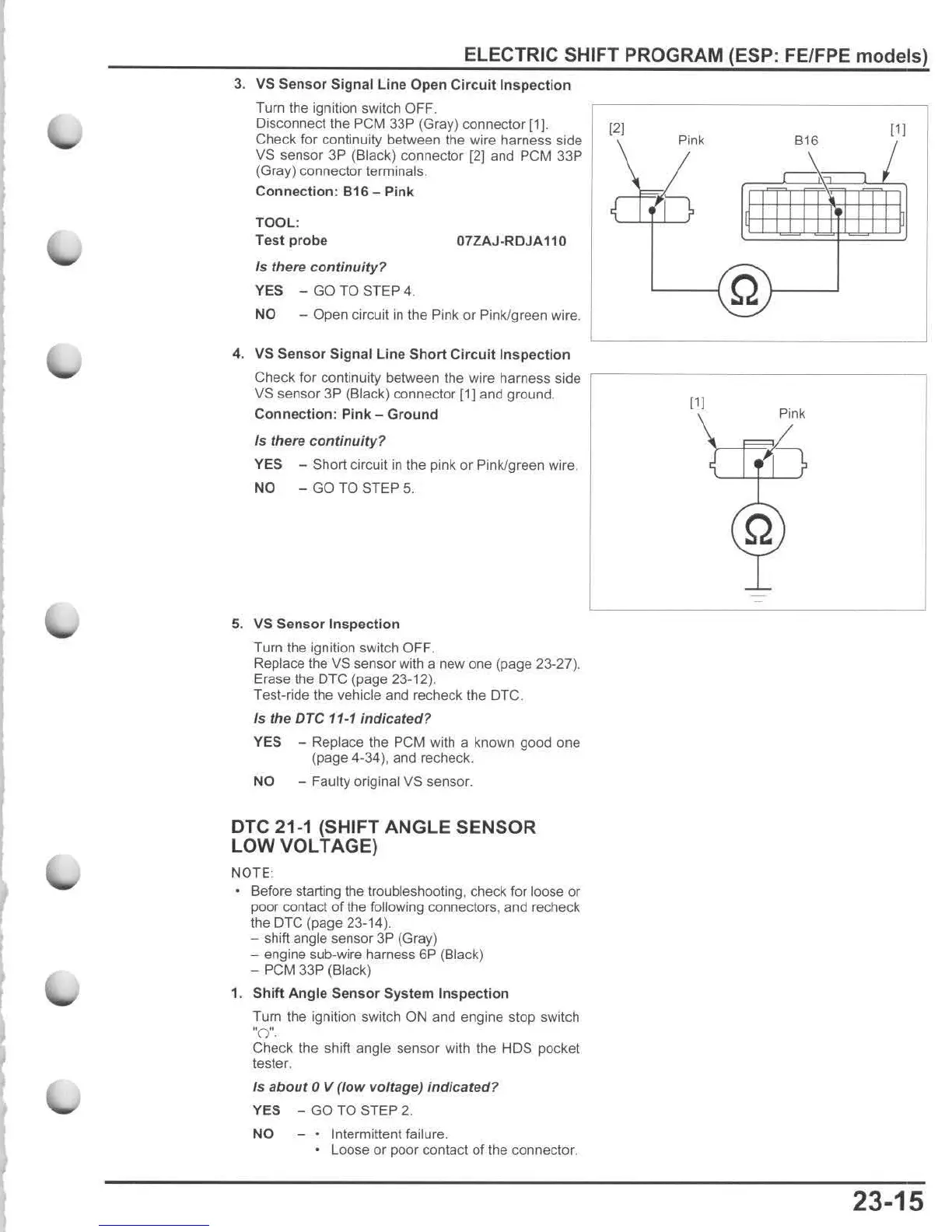
3.
VS
Sensor
Signal
line
Open
Circuit
Inspection
Turn the ignition switch OFF.
Disconnecllhe
peM
33P (Gray) connector
[1).
Check for continuity between the wire harness side
VS sensor 3P (Black) connector
[2J
and
peM
33P
(Gray) connector terminals .
Connection
:
816
- Pink
TOOL:
Test
probe
07ZAJ·RDJA110
Is
there
continuity
'?
YES
- GO TO STEP 4.
NO
- Open circuit in t
he
Pink or Pink./green
wi
re.
4.
VS
Sensor
Signal
line
Short
Circuit
Inspection
Check for continuity between the wire harness side
VS sensor 3P (Black) connector [1] and ground.
Connection
: Pink -
Ground
Is
there c ontinuity?
YES
- Short circuit
in
the pink or Pink/green wire .
NO -
GO
TO STEP
5.
5. VS
Sensor
Inspection
Turn the ignition switch OF F.
Replace the VS sensor
wi
th a new one (page 23-27).
Erase the
DTC (page 23-12).
Test-ride the vehicle and recheck the DTC.
Is
the
ore
11-1
indicated
?
YES - Replace the PCM with a known good one
(page 4-34
),
and recheck.
NO - Faulty original VS sensor.
DTC 21·1 (SHIFT ANGLE SENSOR
LOW VOLTAGE)
NOTE :
Before starting the troubleshooting, check for
loose or
poor contact
of
the following connectors, and recheck
the
DTC (page 23-14).
- shift angle sensor 3P (Gray)
- engine sub-wire harness 6P (Black)
- PCM 33P (Black)
1.
Shift
Angle
Sensor
System
Inspection
Turn the ignition switch
ON
and engine stop switch
·
0·.
Check the shift angle sensor with the HDS pocket
tester.
Is
about
0 V (
low
voltage
)
indicated
?
YES - GO TO STEP 2.
NO Intermittent failure.
• Loose
or
poor contact of the connector.
121
Pink
816
PI
PI
Pink
23-15

 Loading...