Select the
kD
range
of
the tester.
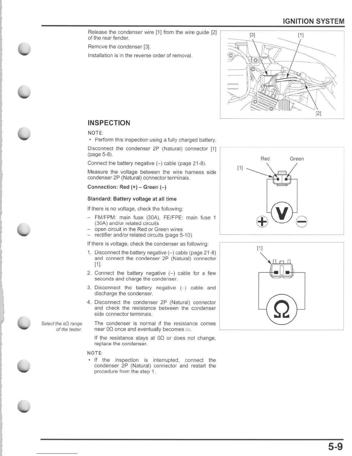
Release the condenser wire [1] from the wire guide [2)
of
the rear fender.
Remove the condenser [3].
Installation
is
in the reverse order of removal.
INSPECTION
NO
TE:
• Perform this inspection using a fully charged battery.
Disconnect the condenser 2P (Natural) connector [lJ
(page 5-8)
Connect the battery negative
(-)
cable (pa ge 21-8).
Measure the voltage between the wire harness side
condenser 2P (Natural) connector terminals.
Connection
: Red (+) - Green
(-)
Standard: Battery
vo
ltage
at
all
time
If there
is
no voltage, check the following:
- FM/FPM: main fuse (30A), FE/FPE: main fuse 1
(30A ) and
lor
related circuits
- open circuit
in
the Red or Green wires
- rectifier and/or related circuits (page 5-10)
If there is voltage, check the condenser as following:
1.
Disconnect the battery negative
(-)
cable (page 21-8)
and connect the condenser
2P
(Natural) connector
111.
2.
Connect the battery negative
(-)
cable for a few
seconds and charge the condenser.
3. Disconnect the battery negative
(-)
cable and
discharge the condenser.
4. Disconnect the
co
ndenser
2P
(Natural) connector
and check the resistance between the condenser
side connector terminals.
The condenser is normal if the resistance comes
[11
near
00
once and eventually becomes
<Xl
. L
___
_
If
the resistance stays
at
00
or does not change,
replace the condenser.
NOTE :
If
the inspection is interrupted, connect the
condenser
2P
(Natural) connector and restart the
procedure from the step
1.
IGNITION SYSTEM
Red
Green
111
Q
5-9

 Loading...