POWER RELAY (Canada type)
RELAY INSPECTION
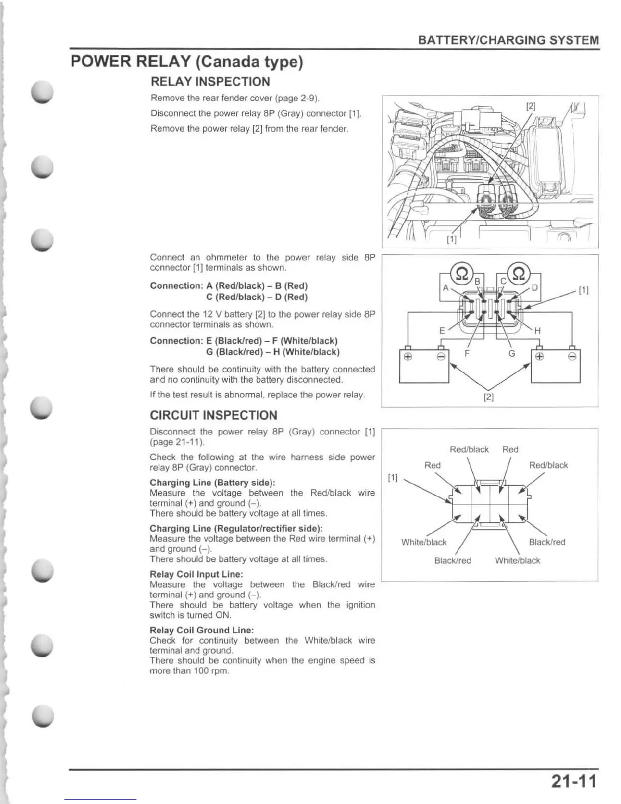
Remove the rear tender cover (page 2-9
).
Disconnect the power relay
BP
(Gray) connector
[1J
.
Remove the power relay
[2J
from the rear fender.
BATTERY/CHARGING SYSTEM
Connect an ohmmeter
to
the power relay side
8P
I
connector
[1]
terminals as shown.
Connection
: A (Red/
bla
ck) - B (Red)
r--S~~I;~~~~::::
111
C (Red/black) - 0 (Red)
Connect the 12 V battery
(2]
to the power relay side
8P
connector terminals as shown.
Connection
: E
(Black/red
) - F
(White/black)
G (BlaCk/red) - H
(White/black)
There should be continuity
wi
th the battery connected
and no continuity with the battery disconnected.
If the test result is abnormal, replace the power relay.
CIRCUIT INSPECTION
Olsconnect the power relay 8P (Gray) connector (1)
r---
(page 21-11).
Redlblack
Red
Check the following al the wire harness side power
relay
8P
(Gray) connector.
Charging
Line
(Battery
side):
Measure
the
voltage between
the
Red/black wire
terminal (+) and ground
(-)
,
There should be battery voltage at all times.
Charging
LIne
(Regulator
/r
ectifier
side):
Measure the voltage between the Red wire terminal (+)
and ground (- ).
There should
be
battery voltage
al
all times.
Relay
Coil
Input
Line
:
Measure the voltage between
the
Black/red
wi
re
terminal
(+
) and ground
(-)
.
There should be battery
voltage when the ignition
switch is turned
ON.
Relay
Coli
Ground
Une:
Check for continuity between the White/black wire
terminal and ground.
There
should
be
continuity when the engine speed is
more than
100 rpm.
111
Rod
Whitelblack
Black/red
Redlbfack
Black/red
White/black
21-11

 Loading...