ELECTRIC POWER STEERING (EPS: FPM/FPE models)
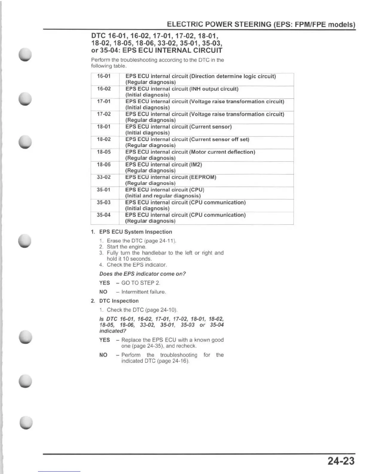
DTC
16-01,16-02
,17-
01,17-02,18-01,
18-02,18-05,18-06, 33-02,35-01 , 35-03,
or
35-04: EPS ECU INTERNAL CIRCUIT
Perform the troubleshooting according to the OTC
in
the
following table.
l
16.01
~
'
E"piiS
'
E"C"U
internal
circuit
(Direction
determine
logic circuit)
(Regular
diagnosis)
16-02 EPS ECU
internal
circuit
(INH
output
circuit)
(Initial
diagnosis)
17..()1
EPS ECU
internal
circuit
(Voltage raise
transformation
circuit)
17..()2
18..()1
r
18"'(}2
18-05
18-06
(Initial
diagnosis)
EP$ ECU
internal
circuit
(Voltage raise
transformation
circuit)
(Regular
diagnosis)
EPS ECU
internal
circuit
(Current
sensor)
(Initial
diagnosis)
==J
EPS ECU internal
circuit
(Current
sensor
off
set)
(Regular
diagnosi
s)
EPS ECU Internal
circuit
(Motor
current
deflection)
(Regular
diagnosis)
EPS ECU
internal
circuit
(
1M2
) I
(Regu
lar
diagnosi
s)
33.()
iC
2
.-+--i
EPS
ECU
internal
circuit
(EEPR'''O'''M")
--
---
(Regular
diagnosis)
35-01 EPS ECU
internal
circuit
(CPU)
(Initial
and
regular
diagnosis)
35.()
1:
EPS ECU
internal
circuit
(CPU
communication)
(Initial
diagnosis)
35-04 EPS ECU Internal
circuit
(CPU
co
mmunication)
(Regular
diagnosis)
1. EPS ECU System
Inspection
1. Erase the
DTG
{page 24·
11
J.
2. Start the engine.
3 Fully
lum
the handlebar
to
the left
or
right and
hold
it
10 seconds.
4. Check the
EPS indicator.
Does the EPS
indicator
come
on?
YES - GO TO STEP 2.
NO - Intermittent failure.
2. OTC
Inspection
1. Check t
he
DIG (page 24-10).
Is
Dre
1S.01, 16-02, 17-01, 17.02, 18-01, 18-02,
18
-05, 18-06, 33-02, 3S.01 , 35-03
or
35-04
indicated?
YES - Replace the EPS
EeU
with a known good
one (page 24-35), and recheck.
NO - Perform the
troubleshooting for
th
e
indicated DTC (page
24
-16).
24-23

 Loading...


