ELECTRIC POWER STEERING (EPS : FPM/FPE
models)
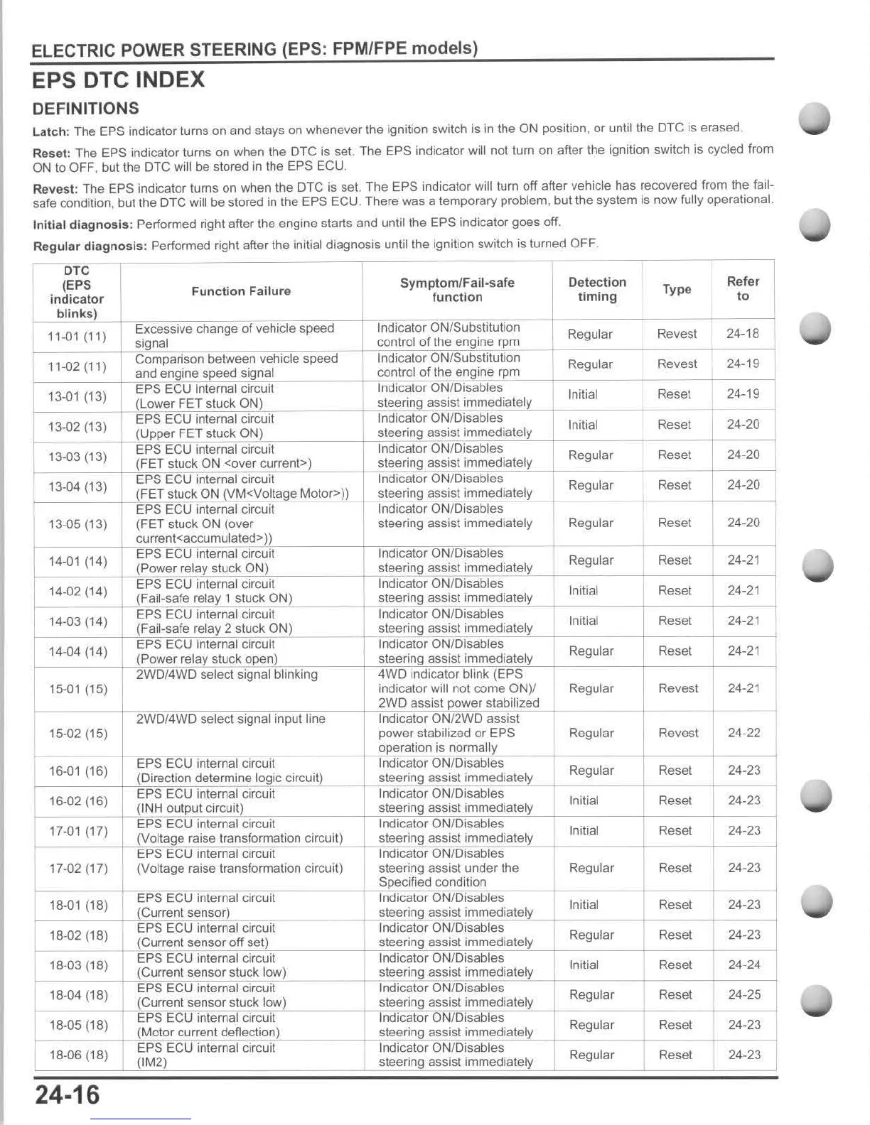
EPS DTC INDEX
DEFINITIONS
Latch
: The EPS indicator turns on and stays on whenever the ignition switch is
in
the ON position, or until the DTG is erased.
R
ese
t: The EPS indicator turns on when the
DIG
is
set
The EPS indicator will not turn on after the ignition switch is cycled from
ON
to
OFF, but the
OTG
will be stored
in
the EPS ECU.
Re
vest:
The EPS indicator turns on when the DTG is sel. The EPS indicator will turn
off
after vehicle has recovered from the fail-
safe condition, but the DTC will be stored
in
the EPS ECU. There
was
a temporary problem. but the system is now fully operational.
Initial
diagnosis
: Performed right after the engine starts and
untillhe
EPS indicator goes off.
Regular
diagnosis
: Performed right after the initial diagnosis until the ignition switch
is
turned OFF.
r--o
TC
--
---,----
--,-
---,
(EPS
indicator
blinks
)
11-01
(II)
Function Failure
Symptom/Fail-safe
function
Excessive change of vehicle speed Indicator ON/Substitution
signal control
of
the engine rpm
Comparison between vehicle speed Indicator ON/Substitution
Detection
timing
Regular
Type
Revest
Refer
to
24-18
11-02 (11)
Regular Revest 24-19
and
en
.gine speed signal control
of
the engine
~,p~m"-
_~
____
-+
___
____
-j
13-01
(13)
EPS
EGU
internal circuit Indicator ON/Disables
Initial
'--
___
_
+_
(Lower FET stuck ON)
__
___
~'~te~e~'~i"~g_":assist
immediately
I 13-02 (13) EPS
EGU
internal circuit Indicator ON/Disables Initial
'--
____
+-
-a*~FDE~T;;;;:~
ON) steering assist
..
im,,",m~e~d~;a~te~ty,--
+
___
_
I 13-03 (13) i circuit Indicator
ON/DTSables
)
_
':--=-"'''-+
~fJ:~~,~k;ON
<over current» steering assist immediately
r 13-04 (13) internal circuit Indicator ON/Disables
I steering assist immediately
13-05 (13)
Indicator ONfDisables
steering assist immediately
assist
Regular
Regular
Regular
Regular
Initial
Initial
Regular
Reset
Reset
Reset
Reset
Reset
Reset
Reset
Reset
Reset
Revest
;;:;~~,~~~
J~
R~e~g~Ular
h
~~~~
-n
~i~
i
-+-
15-02 (15)
16-01
(16)
16-02 (16)
17-01
(17)
17-02 (17)
18-01
(18)
18-02 (18)
18-03 (18)
18-04 (18)
18-05 (18)
18-06 (18)
24·16
i
(Voltage raise transformation circuit)
power stabilized
or
EPS
operation is normally
Indicator
ON/Disables
i
assist under the
assist i i
ONfDisables
i i
;
(Motor current deflection)
EPS
EGU
internal circuit
(tM2)
___
--;
'~te~e2:ring
assist i i
Indicator ONfDisables
steering assist i
Regular
Revest
Regular Reset
Initial Reset
Initial Reset
Regular Reset
Initial Reset
Regular Reset
Initial Reset
Regular Reset
Regular Reset
Regular Reset
24-19
24-20
24-20
24-20
24-20
24-21
24-21
i
24-21
24-21
24-21
24-22
24-23
24-23
24-23
24-23
24-23
24-23
24-24
24-25
-I
24-23
24-23

 Loading...