BATIERY/CHARGING SYSTEM
ALTERNATOR CHARGING COIL
INSPECTION
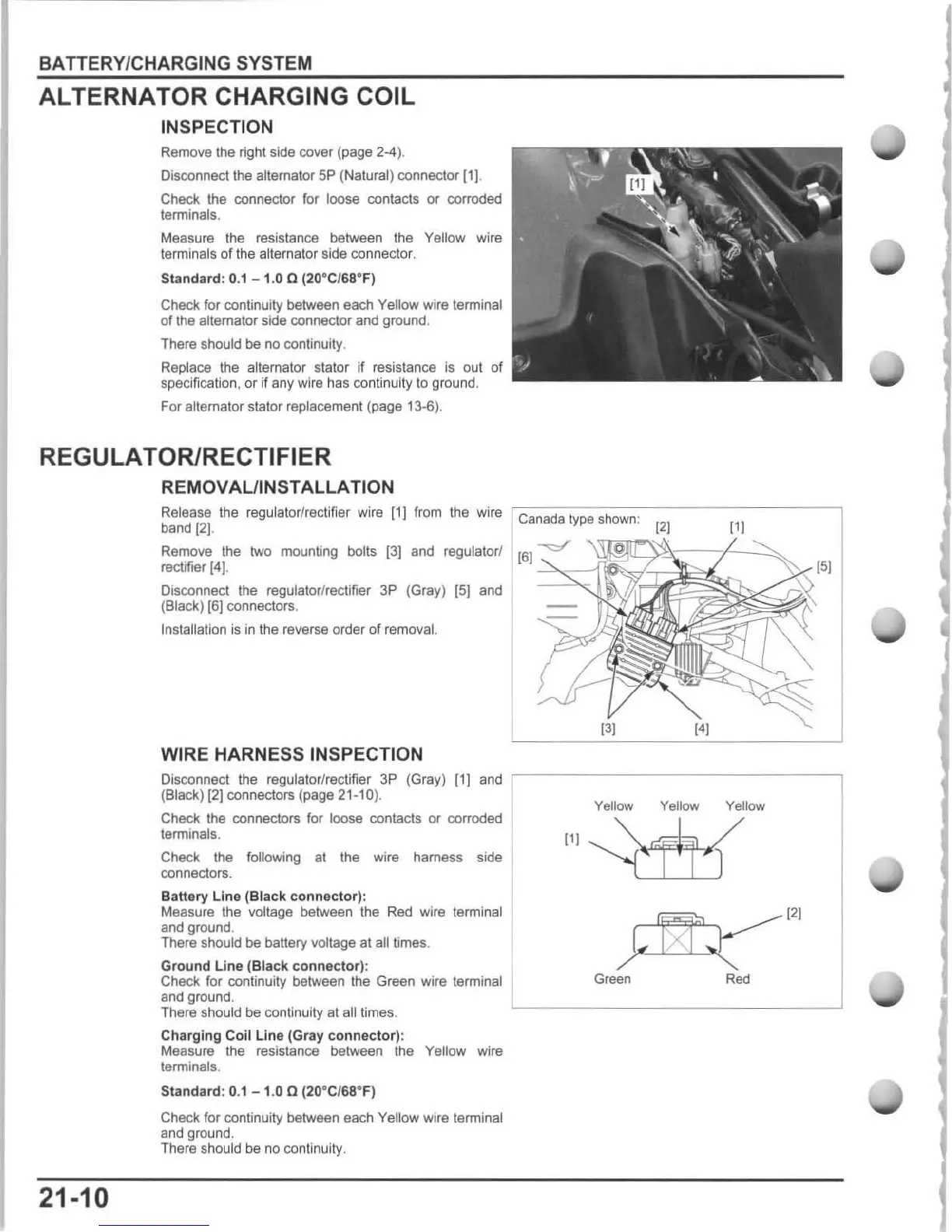
Remove the right side cover (page
24)
.
Disconnect the alternator 5P (Natural) connector (1] .
Check the connector for loose contacts
or
corroded
terminals.
Measure the resistance between the
Yellow wire
terminals
of
the alternator side connector.
Standard
: 0.1 - 1.0 a (20°C/68°
F)
Check for continuity between each Yellow wire terminal
of
the alternator side connector and ground.
There should be no continuity.
Replace the alternator stator if resistance is out of
specification, or
If
any wire has continuity to ground.
For
alternator stator replacement (page 13-6).
REGULATOR/RECTIFIER
REMOVAUINSTALLA TION
Release
the
regulator/rectifier wire
[1)
from the wire Canada type shown:
[2J
band
(2]
.
[11
Remove the
two
mounting bolts
(3]
and regulatorl
(6)
~
rectifier
14)
.
-:::::S;::;;11~~
Disconnect the regulator/reclifier
3P
(Gray) [5] and -
(Black)
16]
connectors.
Installation
is
in the reverse order
of
removal.
13J
[4J
WIRE HARNESS INSPECTION
[5[
Disconnect
the
regulator/rectifier
3P
(Gray) [1]
and
,------------------,
21-10
(Black) [2) connectors (page 21.10).
Check the connectors for loose contacts or corroded
terminals.
Check the following at the wire hamess side
connectors.
Battery
Une
(Black connector):
Measure the voltage between the Red wire termin
al
and
ground.
There should be battery voltage at all times.
Gr
ound
Une
(Black connec
tor
):
Check for continuity between the Green wire terminal
and ground.
There should be continuity at all times.
Charging
Coil
Line
(Gr
ay
c
onnector)
:
Measure the resistance between the
Yellow wire
terminals.
Standard
: 0.1 - 1.0 a (20°C/68-F)
Check
for continuity between each Yellow wire terminal
and ground.
There should be no continuity.
Yellow Yellow Yellow
[11
1Xi
[2J
}X~
Gcee"
Red

 Loading...