ELECTRIC SHIFT PROGRAM (ESP: FE/FPE models)
23-16
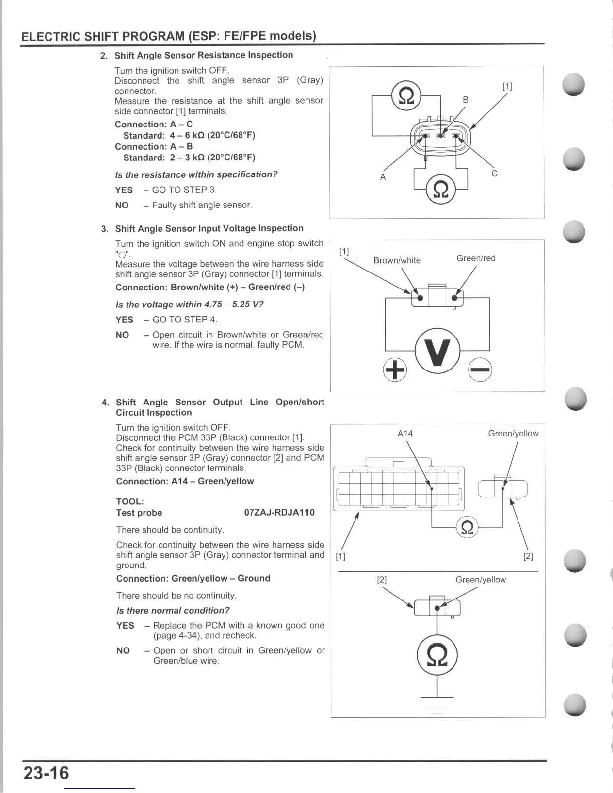
2.
Shift
Angle
Sensor
Resistance
Inspection
Turn the ignition switch OFF.
Disconnect the shift angle sensor 3P (Gray)
connector.
Measure the resistance at the shift
angle sensor
side connector
[11
terminals.
Connection:
A - C
Standard
: 4 - 6 kG (20°C/68°F)
Connection:
A - B
Standard:
2 - 3
kG
(20°C/68°F)
Is the resistance
within
specification?
YES -
GO
TO STEP 3.
NO - Faulty shift angle sensor.
3.
Shift
Angle
Sensor
Input
Voltage
In
spection
111
B
A
c
Turn the ignition switch ON and engine stop switch
,-----
-------
--
---
-
"
0".
11)
Measure the voltage between the wire harness side
shift angle
sensor
3P
(Gray)
connector
(1) terminals.
Connection
:
Brown
f
white
(+) - Green/red
(-)
Is
the voltage
within
4.75 - 5.
25
V?
YES
-
GO
TO
STEP 4.
NO
- Open circuit
in
Brown/white or Green/red
wire. If the wire is normal, faulty
PCM.
4.
Shift
Angle
Sensor
Output
Line
Open/
short
Circuit
Inspection
Turn the ignition swi tch OFF.
Disconnect the PCM 33P (Black) connector
[1
).
Check for continuity between the wire harness side
Brown/white
Green/red
ffiV
e
A14
Green/yellow
shift angle sensor
3P
(Gray) connector
[2]
and
pe
M I
~:::;"i'~~~~~~?:;=;l
33P
(Black)
connector
terminals.
If
Connection
: A14 -
Green/yellow
TOOL:
Test
probe
07ZAJ·RDJA110
There should be continuity.
Check for continuity between the
wi
re harness side
sh
i
ft
angle sensor 3P (Gray) connector terminal and
[11
ground.
Connection:
Green/yellow
-
Ground
There should be no continuity.
Is there
normal
condi
tion
?
YES - Replace the
peM
wi
th a known good one
(page 4-34). and recheck.
NO - Open or short circuit in Green/yellow or
Green/blue wire.
[21
[2)
Green/yellow

 Loading...