FRONT WHEEUSUSPENSION/STEERING
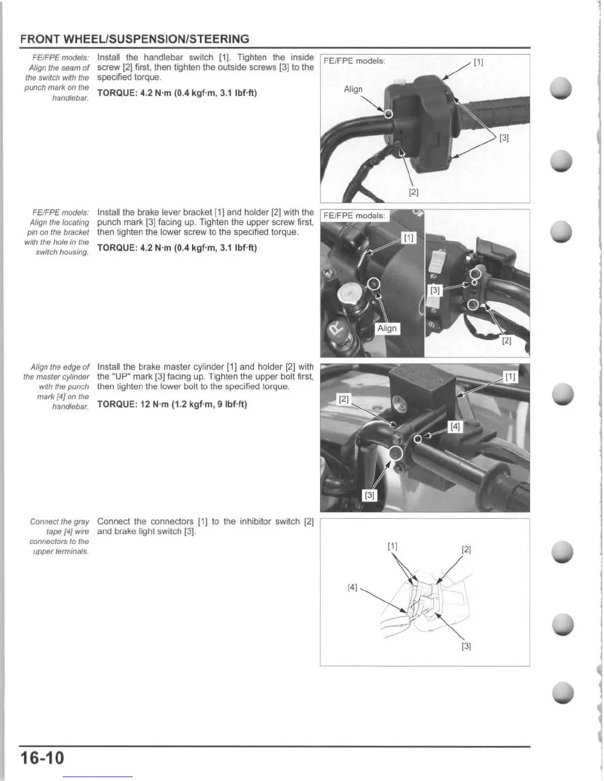
FEJFPE
models:
Allfln the
seam
of
the switch with the
punch mark
on/he
handlebar.
FElFPE models:
Align
the
locating
pm
Of!
the
bracket
with the hole in the
switch housing.
Align the edge
of
the
mas/ef
cylinder
with
the
punch
mark
{4}
on
the
handlebar.
Install the handlebar switch
[1)
. Tighten the inside
screw
[21
first,
th
en
tighten the outside screws
[3]
to the
specified torque.
TORQUE: 4
.2
N'm (0.4
kgf
·m. 3.
1Ibf
·ft)
Instalilhe brake lever b
ra
cket
(1]
and holder
[2)
with the
punch mark
(3)
facing
up
. Tighten the upper screw
fi
rs
t,
then tighten
the
lower screw to the specified torque,
TORQUE : 4.2 N'm
(0
.4
kgf
-m, 3.1 Ibf-ft)
Inslall
the brake master cylinder
(1]
and holder
[2)
with
the
"U
P· mark
[3)
fa
ci
ng
up
. Tighten the upper boll first,
then
tighten the lower bolt
to
the
speCified
torque.
TORQUE: 12 N'm (1.2 k
gf
'm ,
9lbHt
)
COOneG't
the gray Connect the connectors
[1J
to the inhibitor switch
[2J
tape
(4)
Wlf9
and brake tight switch (
3J
.
connectors 10 Ihe
upper terrmna/s.
16-10
I
,
FElFPE models:
[11
11[
121
[4[
/
131

 Loading...