ELECTRIC POWER STEERING (EPS : FPM/FPE models)
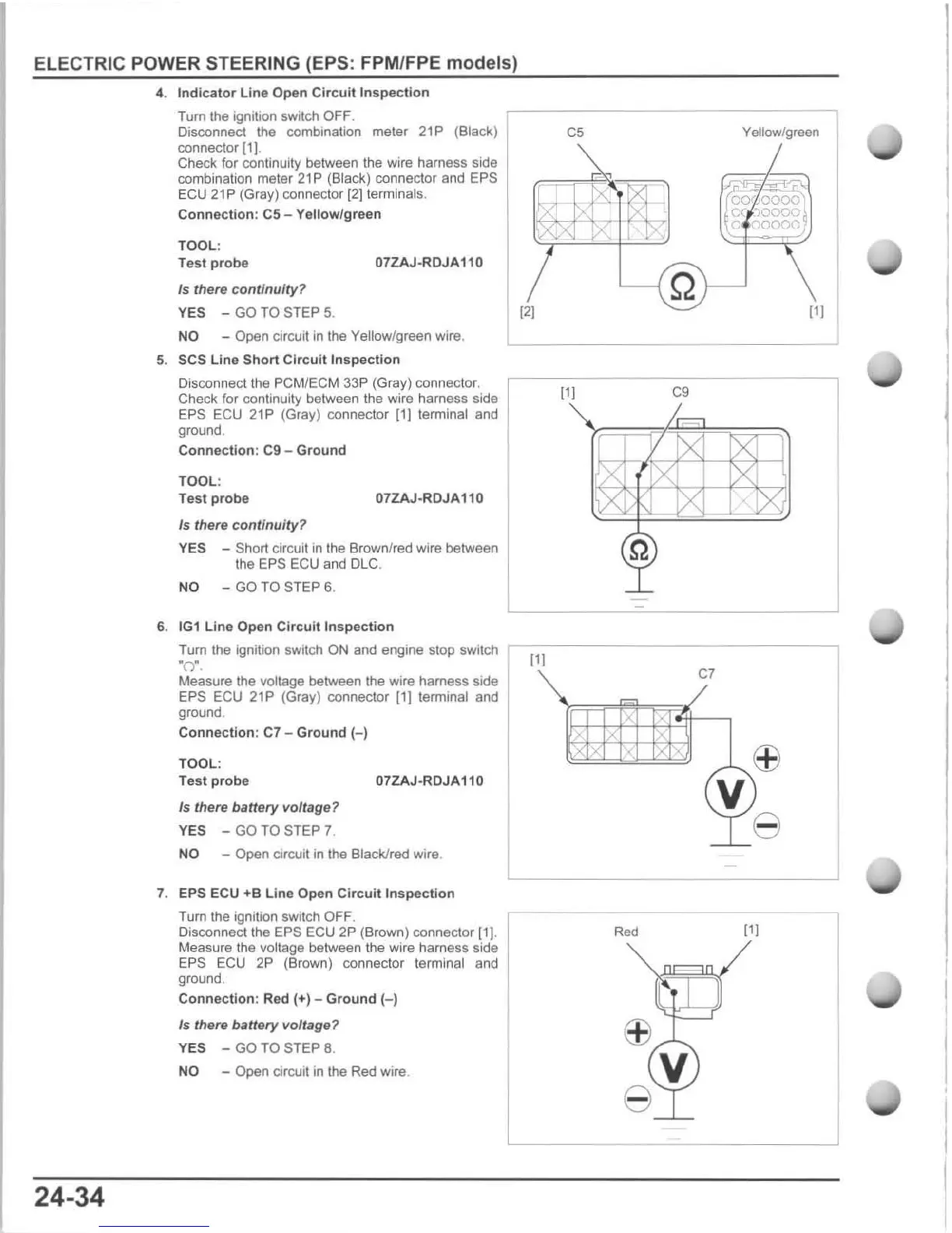
4. Indic
ator
Line Open Circu it
Inspecti
on
Tum
the ignition switch OFF.
Disconnect
the
combination meier 21P (Black)
connector
[1].
Check for continuity between the wire harness side
combination meter
21
P (Black) connector and EPS
ECU 21P
(Gray) connector
121
terminals.
Connection:
C5
- Yellow/green
TOOL
:
Test probe
07ZAJ
·
RDJA110
Is there
co
nt
inuity?
YES - GO TO STEP 5.
NO - Open circuil in the Yellow/green wire.
5. SCS Line Short Circuit Inspection
Disconnect the PCMfECM 33P (Gray) connector.
Check
fo
r continuity between the wire harness side
EPS ECU 21P (Gray) connector [1] terminal and
ground.
Connect
i
on
: C9 -
Ground
TOOL:
Te
st
probe
07ZAJ·ROJA110
Is
there
continu
i
ty
?
YES - Short circuit in the Brown/red wire between
the
EPS ECU and DLC,
NO
- GO TO STEP 6.
6.
IG1
Line Open
Cir
c
uit
Inspe
ction
C5
[21
111
C9
Yellow/green
~
""
00'
000§
oc
)0
000
9
o
r)OOOG
111
Tum
the ignition switch ON and engine stop sWitch
r-
I-'I-
--
-------------'
·0 · ,
24-34
Measure
the
voltage
between
the
wire
harness
side
EP$
EeU
21P
(Gray) connector
111
terminal and
ground .
Connection:
C7
- Ground H
TOOL
:
Test
probe
Is there batte
ry
voltage?
YES -
GO
TO STEP 7.
07ZAJ·RDJA110
NO - Open circuit in the Black/red wire.
7.
EPS ECU
+8
Line
Op
en
Circu
it
Insp
e
ction
Tum
the ignition switch OFF.
Disconnect the EPS ECU 2P (Brown) connector
\11
.
Measure the voltage between the wire harness side
EPS ECU 2P (Brown) connector terminal and
ground.
Conne
c
tion
: Red (+) -
Ground
(-)
Is there battery voltage?
YES -
GO
TO STEP 8.
NO
- Open circuit
in
the Red wire.
C7
Red

 Loading...