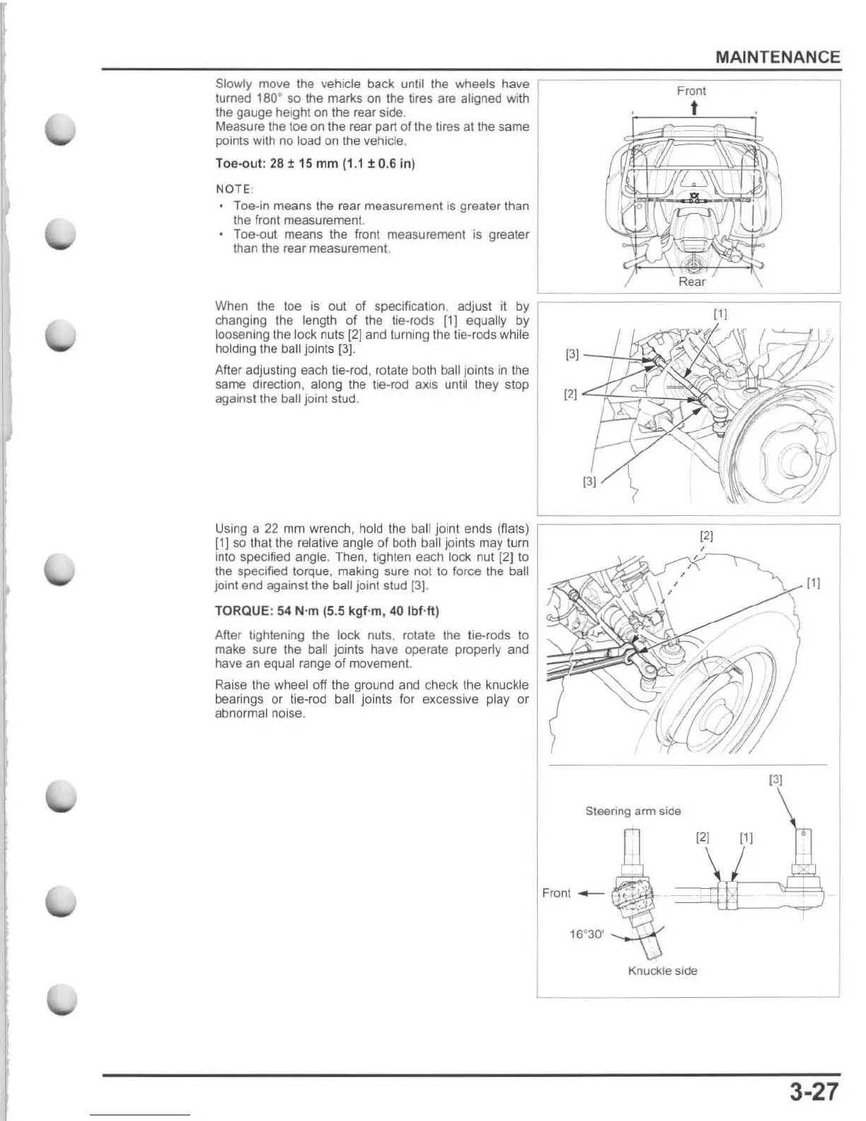
Slowly move
th
e vehide back until
the
wheels have
turned
180
· so the marks on
the
tires are aligned with
the
gauge
height
on
the
rear side.
Measure the toe on the rear part
of
the tires at the same
points with
no
load on the vehicle.
Toe-o
ut
:
28
± 15 mm
(1.1
:t 0.6 in)
NOTE
-
Toe-In means the rear measurement is greater than
the front measurement.
Toe
-out
means
the
front
measurement
is
greater
than the rear measurement.
MAINTENANCE
Front
t
{11
When the loe
is
out of specification, adjust it by r
changing the length
of
the
lie-rods
[1)
equally by
loosening the lock nuts [2] and turning the tie-rods while
holding the ball joints
[3J
.
[3)
After adjusting each lie-rod , rotate both ball joints
in
the
~:~l~~~~r:1~~~
~~~~~;~
same direction, along the lie-rod axis unlil they stop
against the
ball joint stud.
[2]
Using a
22
mm wrench , hold
the
ball joint ends (fla
ts
)
(1)
so
that
the
relative angle
of
both ball joints may tum
into specified angle. Then, tighten each
lock nut
(2
)1
0
the specified torque, making sure nol to force
the
ball
jOint
end against the ball joint slud
[3]
.
TORQUE: 54 N·m (5.5
kgf
·m, 40
Ibf
·
ft
)
After lightening the lock nuts, rotate the tie-rods
to
make sure the ball joints have operate property and
have an equal range
of
movement.
Raise the
wheel off the ground and check the knuckle
bearings
or
tie-rod ball joints for excessive play
or
abnormal noise.
131
[21
Steering arm
side
121
{11
Front
__
'""'<PH
Knuckle side
L
[11
J
3·27

 Loading...