17
OTHER FUNCTIONS
17-22
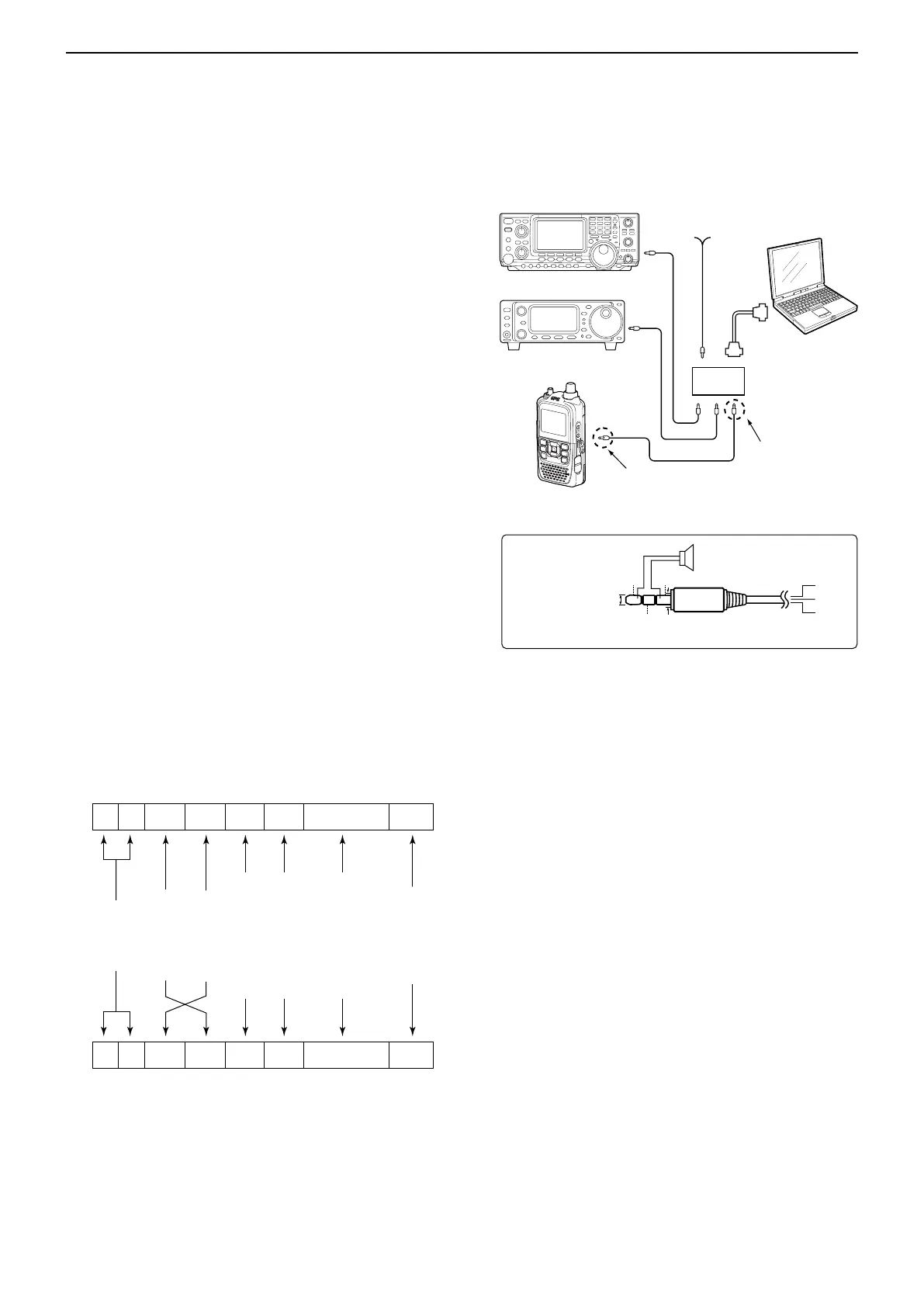
D Data format
The CI-V system can be operated using the following
data formats. Data formats differ depending on com-
mand numbers. A data area or sub command is added
to some commands.
■ CI-V information
CI-V data setting D
Set the ID-51A/E’s address, data transferring speed
and transceive function. See page 16-70 for setting the
CI-V condition using the MENU list screen.
Function > CI-V
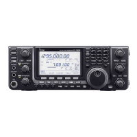
D CI-V connection example
The transceiver can be connected through an optional
CT-17 c i -v l e v e l c o n v e r t e r to a PC equipped with an
RS-232C port.
The Icom Communications Interface-V (CI-V) controls
the transceiver.
Up to 4 Icom CI-V transceivers or receivers can be con-
nected to the PC.
See the CT-17 instruction manual for details of remotely
control a transceiver or receiver.
* Use the cable described at right. No received audio is heard
when the supplied control cable, coming with CT-17, is used
for the connection.
CT-17
Powersupply
9V〜15VDC
RS-
232
C
cable
ID-51A/E
personal
computer
GND
I/O
SP
SP
GND
SP
I/O
¡Connections (ID-51A/E side)
*No speaker is necessary for the CT-17 side.
3-conductor 3.5(d) mm
plug must be used.
2-conductor 3.5(d) mm
plug must be used.
3.5(d)mm
Less than 4.5(d)mm
Controller to ID-51A/E
FE FE 86 E0 Cn Sc Data area FD
Preamble
code (fixed)
Transceiver’s
default address
Controller’s
default address
Command number
(see the command table)
Sub command number
(see the command table)
BCD code data such as
for frequency, memory
number entry
(see the data content description)
End of message
code
(fixed)
ID-51A/E to controller
qwerty u
FE FE E0 86 Cn Sc Data area FD
qwer* ty u
*The reply messages from the transceiver are the command “FB” (OK)
or “FA” (NG).

 Loading...