7-1
Section 7
D-STAR INTRODUCTION
IMPORTANT!
• The repeater list, described in this manual, may differ from your transceiver’s preloaded contents.
• Although Japanese repeaters are used in the setting examples, the Japanese repeater node (port) letters are dif-
ferent from other country’s.
Be sure to add a repeater node letter as the 8th digit in the call sign field after a repeater call sign, according to
the repeater frequency band, as shown below.
1200 MHz : A (B in Japan)
430 MHz : B (A in Japan)
144 MHz : C (no D-STAR repeaters in Japan)
D-STAR Intoroduction ■ .......................................... 7-2
About the DR (D-STAR Repeater) mode ■ ............. 7-2
Communication Form in the DR mode ■ ................ 7-3
To begin the digital mode communication except in the
DR mode, you can use the VFO mode, Memory mode
and Call channel mode.
This manual describes focusing on the DR mode op-
eration which can be set up easily, and if you want to
use another mode, see the procedures as described
to the right.
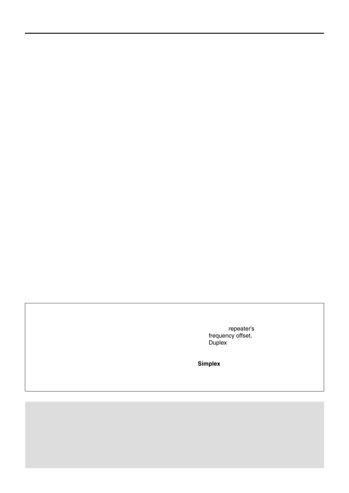
For a Local area call or Gateway call:
Set the access repeater’s frequency. (p. 15-2) q
Set the frequency offset. (p. 15-4) w
Set the Duplex direction. (p. 15-5) e
Set the call signs. (p. 16-48) r
For a Simplex call:
Set the operating frequency. q
Set the call sign. (p. 16-48) w
To begin the digital mode communication except in the DR mode

 Loading...