2-8Operation panel (O/P) functions (CR760 controller)
2Explanation of functions
2.2 Operation panel (O/P) functions (CR760 controller)
(1) Description of the operation panel button
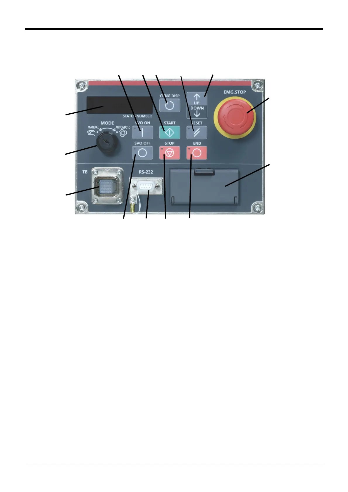
Fig.2-2:Operation panel
<1>
START button .......................This executes the program and operates the robot. The program is run continuously.
<2>STOP button .........................This stops the robot immediately. The servo does not turn OFF.
<3>RESET button.......................This resets the error. This also resets the program's halted state and resets the pro-
gram.
<4>Emergency stop switch.........This stops the robot in an emergency state. The servo turns OFF.
<5>CHNGDISP button................This changes the details displayed on the display panel in the order of "Override"→
"Line No."→"Program No." → "User infomation"→ "Maker infomation".
<6>END button ...........................This stops the program being executed at the last line or END statement.
<7>SVO.ON button.....................This turns ON the servo power. (The servo turns ON.)
<8>SVO.OFF button................... This turns OFF the servo power. (The servo turns OFF.)
<9>STATUS NUMBER
(display panel) .......................The alarm No., program No., override value (%), etc., are displayed.
<10>MODE key switch ...............This changes the robot's operation mode.
AUTOMATIC......................operations from the controller or external equipment are valid. Operations for
which the operation mode must be at the external device or T/B are not
possible. It is necessary to set the parameter for the rights of operation to
connection between the operation panel and external equipment. For details,
please refer to Page 11, "2.3.1 Operation rights".
MANUAL............................When the T/B is valid, only operations from the T/B are valid. Operations for
which the operation mode must be at the external device or controller are not
possible.
<11>
UP/DOWN button ...............This scrolls up or down the details displayed on the "STATUS. NUMBER" display panel.
<12>T/B connection connector ..This is a dedicated connector for connecting the T/B. When not using T/B, connect
the attached dummy connector.
<13>Interface cover ...............USB interface and battery are mounted. Unused in CR760-Q controller.
<14>RS-232 connector
...........This is an RS-232 specification connector for connecting the personal computer. Not
installed in the CR760-Q controller.
<12>
<1>
<3>
<4>
<5>
<7>
<11>
<10>
<9>
<8>
<13>
<6>
<2><14>
 Loading...