7Appendix
Spline interpolation Appendix-641
(8) Editing the spline file
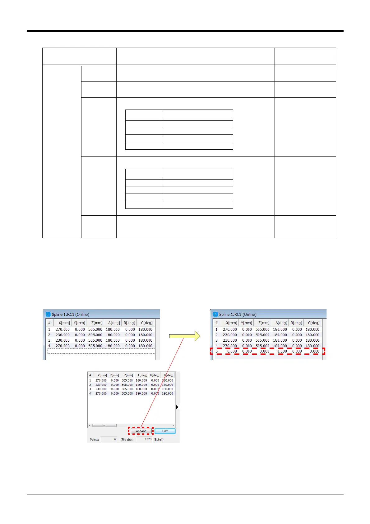
■Adding path point data
If the [Append] button in the path point data list area is clicked, new path point data is added to the end of
the list.
The default values are the values shown in Table 7-12 "Default value when newly added".
(A line can also be added by clicking the menu [Edit]
→ [Append].)
Fig.7-52:Adding path point data
Select random path point data and click the right mouse button. The context menu will open, so click [Insert].
New path point data will be inserted before the selected path point data.
(A line can also be added by clicking menu [Edit]
→ [Insert].)
Output signal Head No. Designate the head address of the output signal.
Setting range: –1 to 32767 (–1 means signal output invalid.)
-1
Bit width Designate the bit width of the output signal.
Setting range: 1, 8, 16, 32 [bit]
1
Bit mask Designate the mask pattern of the bit with valid signal output. 0
Setting value Designate the data to be signal output. 0
Pulse output Designate the pulse output.
Setting range: Check (designation enabled), No check (designation
invalid)
No check
Data item Details
Default value when
newly added
Bit width Setting range [hex]
1 0, 1
8 0 to FF
16 0 to FFFF
32 0 to FFFFFFFF
Bit width Setting range [hex]
1 0, 1
8 0 to FF
16 0 to FFFF
32 0 to FFFFFFFF
 Loading...