Appendix-624 Spline interpolation
7Appendix
Fig.7-21:Numerical setting
(5) Frame transformation
Frame transformation is a function applied on a random path, and moves the path to another position while
maintaining the shape.
The following processes can be handled with this function:
• Transformation from position on drawing to actual position
• Adjustment of work target’s position deviation
• Change of work area with spline interpolation
■Outline of process
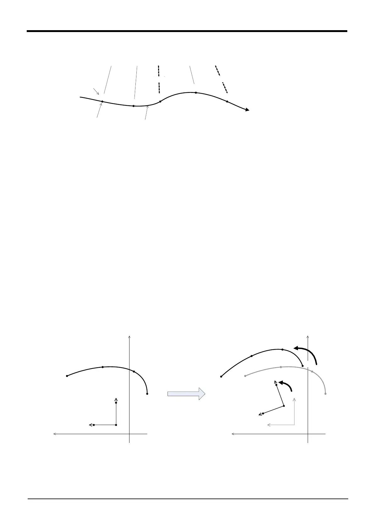
Frame transformation is explained using Fig. 7-22 as an example.
Set a coordinate system to be used as a reference in respect to a random path. The coordinate system is
designated with three position data in the same manner as the Fram function. In this example, position data
PR1, PR2 and PR3 are designated, and reference coordinate system "Xfr-Zfr-Yfr" is set.
Next, set the transformed reference coordinate system in the same manner. In this example, position data
PC1, PC2 and PC3 is designated, and the transformed reference coordinate system "Xfc-Zfc-Yfc" is set.
When frame transformation is executed, all path points are calculated so that the relative displacement from
the reference coordinate system’s origin to the path point is the same before and after the transformation. In
the example, the path points P11 ~ P14 to P21 ~ P24 is calculated.
The same value as the corresponding pre-transformation path points are set for the transformed path point
configuration flags, multi-rotation flags and additional axis data.
In Ex-T spline interpolation, frame transformation is executed including "XE1-ZE1-YE1" of the Ex-T coordi-
nate system origin.
Fig.7-22:Frame transformation (Spline interpolation)
数値設定
(未設定)
M_SplVar = 100 ・・・・・・ 200 ・・・・ 200 ・・・・・・・・ 400 ・・・・・・ 400 ・・・・・
スプライン補間
経路点
100
200
-1 -1
400
(未設定)
Numerical setting
Path point
Spline interpolation
(Not set)
(Not set)
+Xfr
+X
+Y
P11
P12
P13
P14
+Yfr
PR1
PR2
PR3
Zfr
+Xfr
+X
+Y
P11
P12
P13
P14
+Yfr
フレーム変換
Zfr
+
X
f
c
P
2
1
P
2
2
P
2
3
P
2
4
+
Y
f
c
P
C
1
P
C
2
P
C
3
Z
f
c
 Loading...