2
SYSTEM CONFIGURATION
2.1 System Configuration
2.1.4 Overview of system configuration
2 - 7
1
OVERVIEW
2
SYSTEM
CONFIGURATION
3
SPECIFICATIONS
4
FUNCTIONS
5
SETTING AND
PROCEDURES
6
I/O NUMBER
ASSIGNMENT
7
MEMORIES AND
FILES
8
INSTALLING /
UNINSTALLING
Precautions
• Do not use extension cables longer than the overall length of 13.2m
(43.31ft.).
• When using an extension cable, keep it away from the main circuit (high
voltage and heavy current) line.
• Set the number of extension stages so that the number is not duplicated with
another.
• The Q6 RB or QA1S6 B cannot be used as an extension base unit.
• Connect the extension cable from OUT of the extension cable connector of
the base unit to IN of the extension base unit on the next stage.
• An error occurs if the number of mounted modules is 65 or more.
• Bus connection of the GOT is not available.
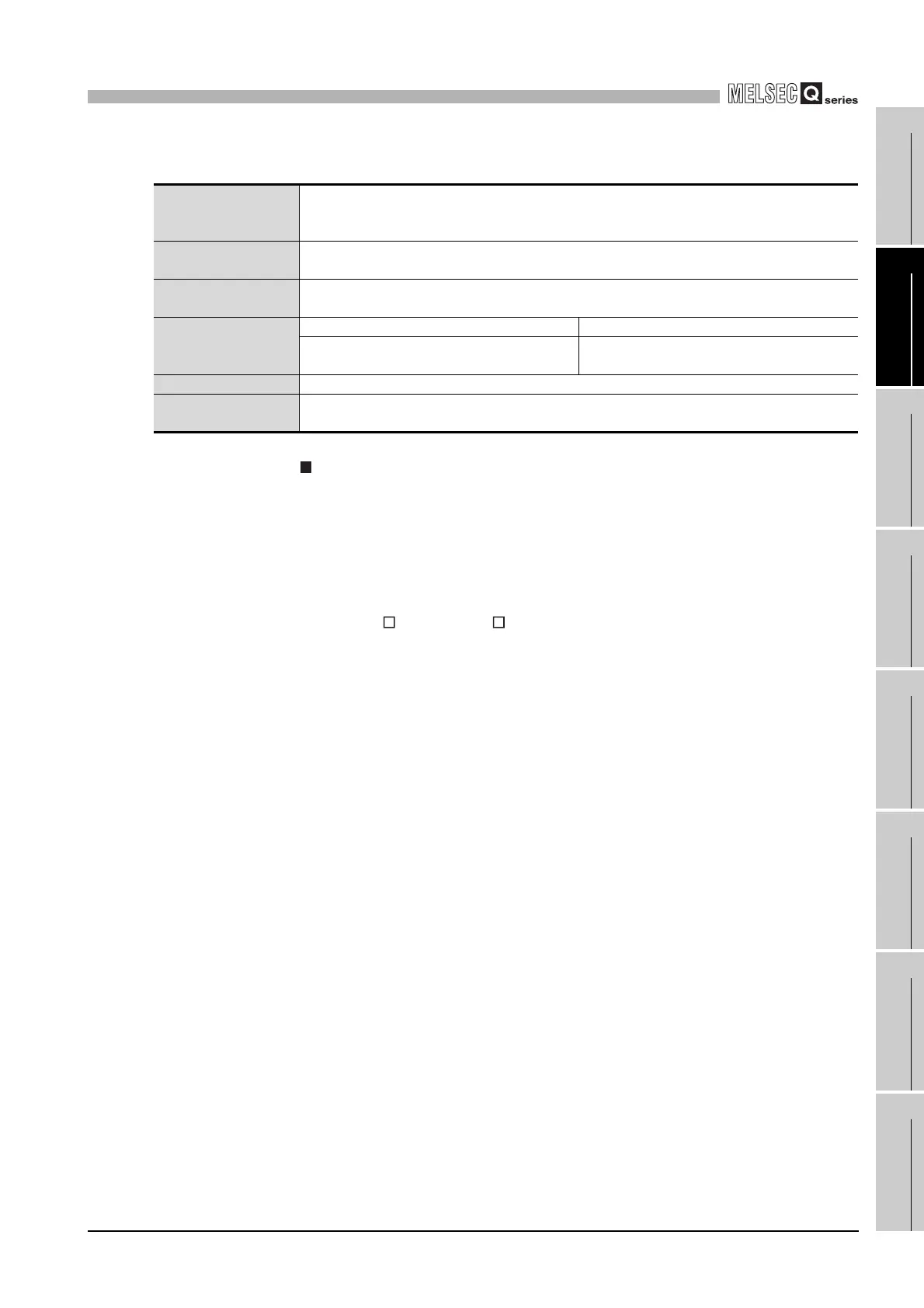
Table2.1 Restrictions on the system configuration, and available base units, extension cables and power supply
modules
Maximum number of
extension stages of
extension base units
7 extension stages
Maximum number of
mounted I/O modules
64 modules
Available main base unit
model
Q33B, Q35B, Q38B, Q312B
Available extension
base unit model
Module types requiring no power supply module Q52B, Q55B
Module types requiring a Q series power supply
module
Q63B, Q65B, Q68B, Q612B
Extension cable QC05B, QC06B, QC12B, QC30B, QC50B, QC100B
Q series power supply
module
Q61P-A1, Q61P-A2, Q61P, Q62P, Q63P, Q64P

 Loading...


