2 - 6
2.1 System Configuration
2.1.4 Overview of system configuration
2
SYSTEM CONFIGURATION
2.1.4 Overview of system configuration
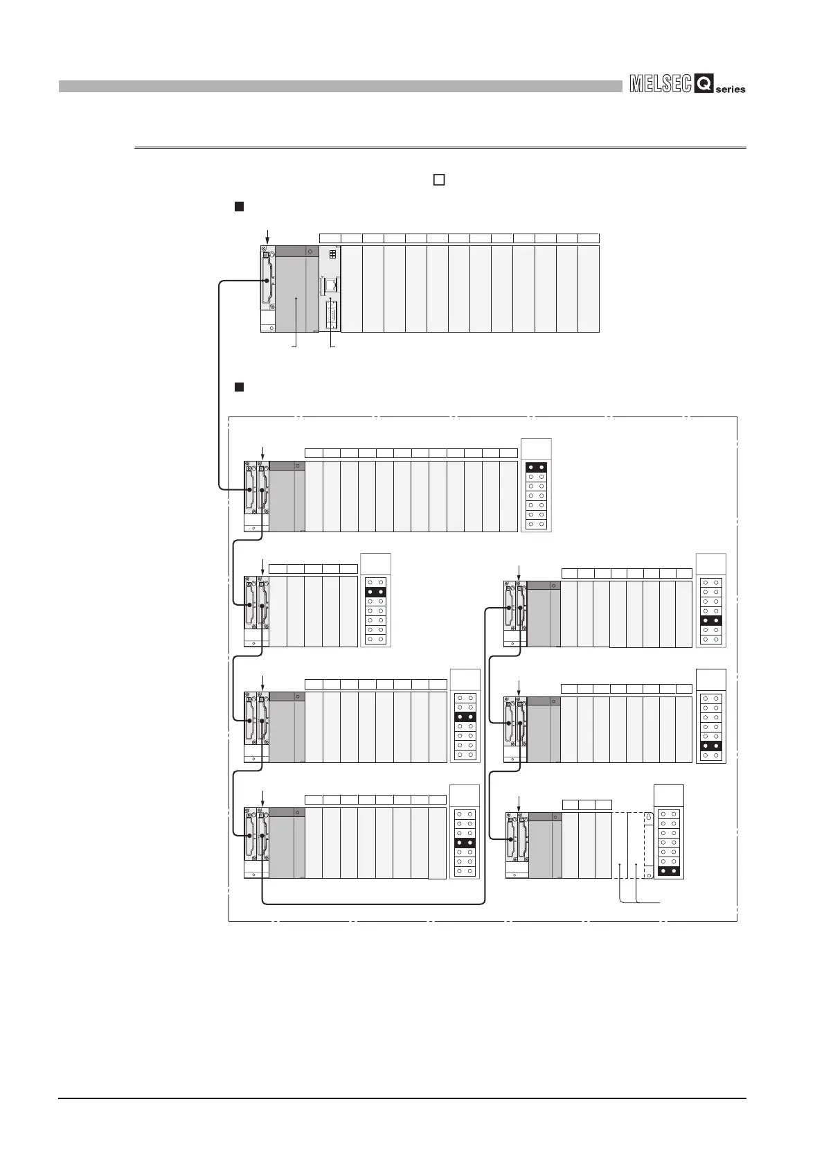
(1) When the main base unit (Q3 B) is used
Figure 2.5 System configuration examples when main base unit is used
Q series
power supply
module
1st
extension
base
2nd
extension
base
5th
extension
base
6th
extension
base
7th
extension
base
3rd
extension
base
4th
extension
base
Q312B (12 slots occupied)
Q612B (12 slots occupied)
Extension base unit When 32-point modules are loaded to slots.
Main base unit When 32-point modules are loaded to slots.
Q55B (5 slots occupied)
Q68B (8 slots occupied)
Q68B (8 slots occupied)
Q68B (8 slots occupied)
Q68B (8 slots occupied)
Q65B (5 slots occupied)
When module is
mounted an error
occurs.
00 to 1F
20 to 3F
40 to 5F
60 to 7F
80 to 9F
A0 to BF
C0 to DF
E0 to FF
100 to 11F
120 to 13F
140 to 15F
160 to 17F
180 to 19F
1A0 to 1BF
1C0 to 1DF
1E0 to 1FF
200 to 21F
220 to 23F
240 to 25F
260 to 27F
280 to 29F
2A0 to 2BF
2C0 to 2DF
300 to 31F
320 to 33F
340 to 35F
360 to 37F
380 to 39F
3A0 to 3BF
3C0 to 3DF
3E0 to 3FF
400 to 41F
420 to 43F
4A0 to 4BF
4C0 to 4DF
4E0 to 4FF
500 to 51F
520 to 53F
540 to 55F
560 to 57F
580 to 59F
440 to 45F
460 to 47F
480 to 49F
5A0 to 5BF
5C0 to 5DF
5E0 to 5FF
600 to 61F
620 to 63F
640 to 65F
660 to 67F
680 to 69F
6A0 to 6BF
6C0 to 6DF
6E0 to 6FF
7A0 to 7BF
7C0 to 7DF
7E0 to 7FF
700 to 71F
720 to 73F
740 to 75F
760 to 77F
780 to 79F
2E0 to 2FF
CPU01234567891011
12 13 14 15 16 17 18 19 20 21 22 23
24 25 26 27 28
45 46 47 48 49 50 51 52
53 54 55 56 57 58 59 60
61 62 63
29 30 31 32 33 34 35 36
37 38 39 40 41 42 43 44
Prohibited
Prohibited
....
I/O number
....
Slot number
...
...
C Controller module

 Loading...


