1
OVERVIEW
1 - 1
1
OVERVIEW
2
SYSTEM
CONFIGURATION
3
SPECIFICATIONS
4
FUNCTIONS
5
SETTING AND
PROCEDURES
6
I/O NUMBER
ASSIGNMENT
7
MEMORIES AND
FILES
8
INSTALLING /
UNINSTALLING
CHAPTER1 OVERVIEW
This manual explains the specifications, functions, and operating procedures of the
MELSEC-Q series compatible C Controller module, as well as the specifications of the
utilities and functions offered by the Module setting/monitoring tools for C Controller
module (SW PVC-CCPU), and the troubleshooting, etc.
Remark
This manual explains the C Controller module.
Refer to the following manual for the details of the C Controller system listed
below.
QCPU User's Manual (Hardware Design, Maintenance and Inspection)
When referring to the manual, read the "CPU module" as the "C Controller
module", and the "Programmable controller" as the "C Controller system".
* 1 To conform the C Controller module to the EMC Directive, it must satisfy the criteria for the noise
immunity standards of the Ethernet and RS-232 cables.
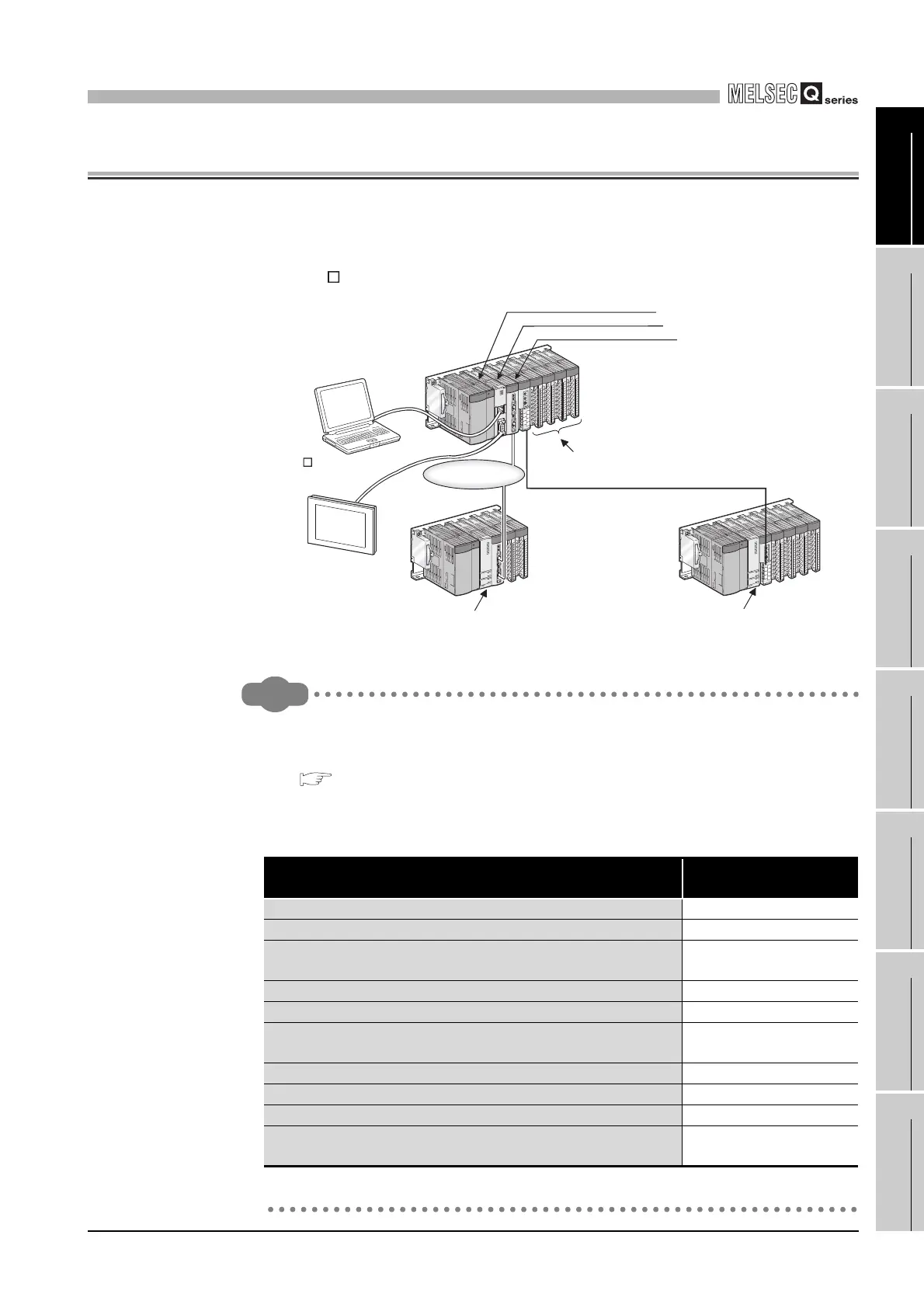
Figure 1.1 System example using C Controller module
Table1.1 Reference list
Item
Reference to related
manual
Using or selecting the power supply module Chapter 5
Using, selecting or setting the base unit or extension cable Chapter 6
Conforming the C Controller system to the EMC and Low Voltage
Directives
Chapter 9
*1
Calculating the heat value of the C Controller system Section 10.2
Mounting the module Section 10.3
Knowing how to set the extension stage numbers for extension
base units
Section 10.4
Connecting or disconnecting extension cables Section 10.5
Wiring the power supply module Section 10.6
Checking problem examples of the I/O module Section 12.5
Checking external dimensions of the power supply module and/or
base unit
Appendix 1
GOT
CC-Link
MELSECNET/H
SW PVC-CCPU
Tornado
Development environment
(personal computer)
C Controller module
MELSECNET/H module
CC-Link module
Access by MELSEC
data link function!
Access by MELSEC
data link function!
Access by bus interface function!

 Loading...


