3
SPECIFICATIONS
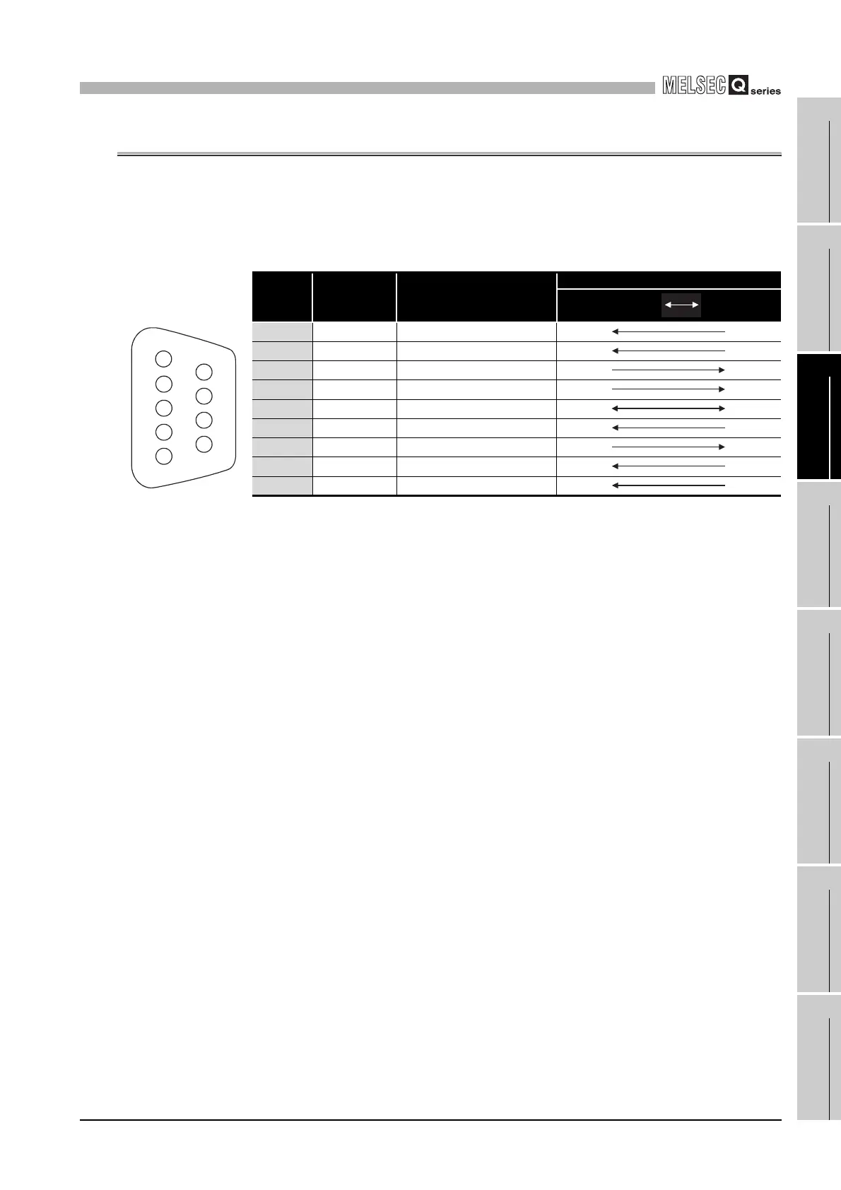
3.3 RS-232 Connector Specifications
3 - 4
1
OVERVIEW
2
SYSTEM
CONFIGURATION
3
SPECIFICATIONS
4
FUNCTIONS
5
SETTING AND
PROCEDURES
6
I/O NUMBER
ASSIGNMENT
7
MEMORIES AND
FILES
8
INSTALLING /
UNINSTALLING
3.3 RS-232 Connector Specifications
The RS-232 connector specifications are shown below.
(1) RS-232 connector specifications
(2) RS-232 interface connector
The C Controller module uses the following RS-232 interface connector.
• DDK Ltd.
9-pin D-sub (female) screw type
17L-10090-27 (D9AC) (-FA)
Use the following as the connector shell of the connector cable of the C Controller
module side.
• DDK Ltd.
Plug, shell: 17JE-23090-02 (D8A) (-CG)
• Connector fitting screw (M2.6)
Table3.3 RS-232 connector specifications
Pin No.
Signal
abbreviation
Signal name
Signal direction
C Controller
module
Modem
1 CD(DCD) Data Carrier Detect
2 RD(RXD) Received Data
3 SD(TXD) Transmitted Data
4 ER(DTR) Data Terminal Ready
5 SG(GND) Signal Ground
6 DR(DSR) Data Set Ready
7 RS(RTS) Request To Send
8 CS(CTS) Clear To Send
9 CI(RI) Ring Indicator
1
2
3
4
5
6
7
8
9

 Loading...


