Duplex Unit
D062/D063/D065/D066 4-80 SM
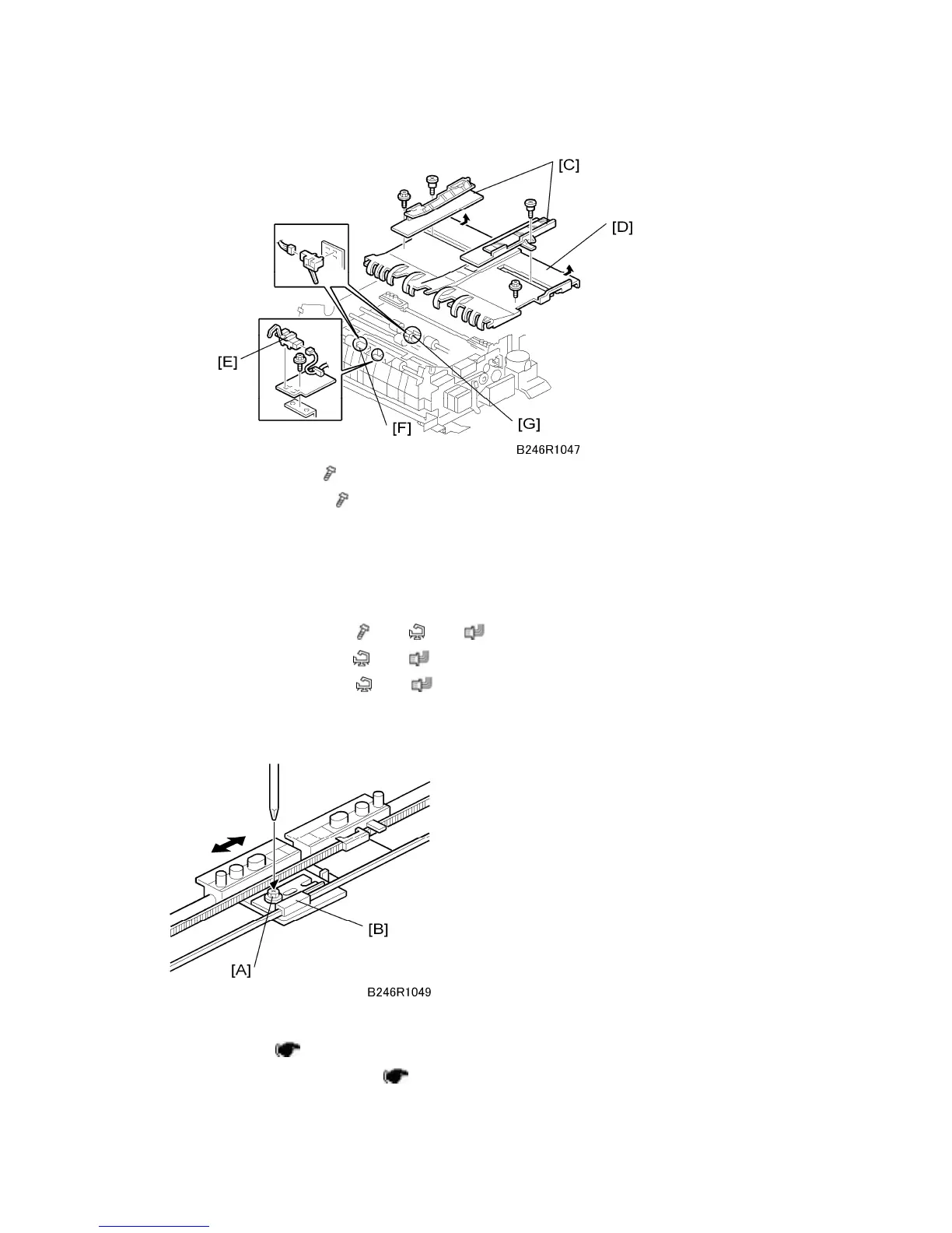
3. Jogger fences [C] (
x 1 each)
4. Left half of table [D] (
x 2)
The front screw is a shoulder screw. Insert the screws in the correct holes when
re-attaching.
To avoid breaking the tabs under the left edge of the table, pull the table to the right
to disengage the tabs and then remove.
5. Inverter exit sensor [E] (
x 1, x 1, x 1)
6. Transport sensor 1 [F] (
x 1, x 1)
7. Transport sensor 2 [G] (
x 1, x 1)
4.10.6 DUPLEX JOGGER BELT ADJUSTMENT
Remove:
Cross stay (
p.4-79 "Inverter Exit Sensor, Transport Sensors 1 & 2")
Reverse trigger roller shaft (
p.4-79 "Inverter Exit Sensor, Transport Sensors 1 &
 Loading...