Home
Ricoh
Copier
D017
Ricoh D017 User Manual
4
of 1
of 1 rating
1271 pages
Give review
Manual
Specs
To Next Page
To Next Page
To Previous Page
To Previous Page
Loading...
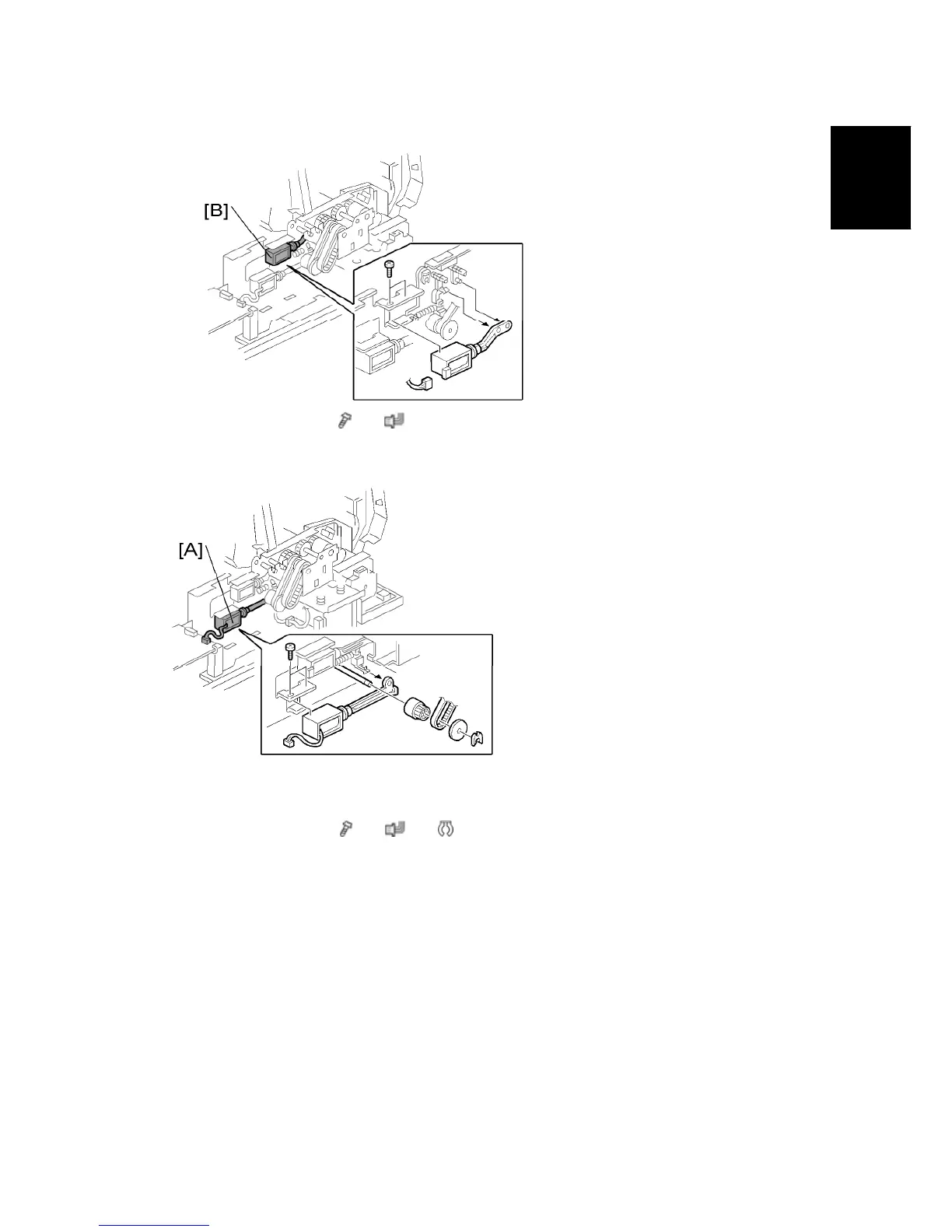
Original Feed Drive
SM 9
D366
ARDF DF3030
D366
3.
Pick-up solenoid [B] (
x 2,
x 1)
1.4.3 INVERTER
SOLENOID
1.
Rear cover (see "Rear Cover")
2.
Harness guide (see "Pick-up Solenoid")
3.
Inverter solenoid [A] (
x 2,
x 1,
x 1, gear x 1, gear cover x 1)
1056
1058
Table of Contents
D017/D018/D019/D020/D084/D085
13
Default Chapter
13
Table of Contents
13
Handling Toner
28
Laser Safety
29
Product Information
36
Installation
47
Specifications
35
Machine Configuration
36
System Configuration and Options
36
Mechanical Components
41
Paper Path
43
Installation Requirements
47
Machine Level
47
Minimum Space Requirements
48
Power Requirements
49
Copier Installation
50
Installation Flow Chart
50
Power Sockets for Peripherals
50
Accessory Check
52
Tapes and Retainers
54
Toner Bottle
58
Transporting the Machine
62
Installation Procedure
64
Sp Mode Settings for Ieee 802.11A/G Wireless Lan
143
File Format Converter Type E (D)
146
Hdd Encryption Unit
148
Recovery from a Device Problem
151
More about Hdd Encryption Unit (D)
153
Before You Begin
156
Data Overwrite Security Unit (D)
156
Seal Check and Removal
157
Browser Unit Type D (D)
160
VM Card Type F (D)
162
Printer and P/S Options (Only for D017/D)
165
Description Qty
167
Rpcs Pu P/S
167
SD Card Yes Yes Yes
167
EU Keytop Set*3
167
NA Keytop Set*3
167
Ferrite Core no Yes Yes
167
3: the Number of Keytops Provided Varies
167
Copy Document Server
168
Keytops
168
Kit
168
RPCS Unit
168
Printer Enhance, Scanner Enhance Options
172
Preventive Maintenance
175
Main Motor Drive Gear
178
Replacement and Adjustment
179
Special Tools and Lubricants
181
General Cautions
182
Pcu (Photoconductor Unit)
182
Fusing Unit
183
Laser Unit
183
Paper Feed
183
Scanner Unit
183
Exposure Glass
185
Original Length/Width Sensors
186
Exposure Lamp
187
Scanner Motor
190
Sensor Board Unit (Sbu)
191
Exposure Lamp Stabilizer
193
When Reassembling
193
Front Scanner Wire
194
Reinstalling the Front Scanner Wire
194
Rear Scanner Wire
197
Reinstalling the Rear Scanner Wire
197
Touch Panel Position Adjustment
198
Caution Decal Locations
199
Polygon Mirror Motor
202
Laser Synchronization Detector
203
Photoconductor Unit (Pcu)
204
Pick-Off Pawls
205
Charge Roller, Cleaning Roller
207
Cleaning Blade
208
After Replacement of Pcu Components
213
Transfer Roller Unit
215
Transfer Unit
215
Image Density Sensor
216
Hot Roller and Fusing Lamps
220
Pressure Roller/Cleaning Roller
223
Paper Exit Sensor/Paper Overflow Sensor
224
Friction Pad
226
Paper End Sensor
227
Paper Tray Lift Motors
228
Registration Clutch
229
Lower Paper Feed Clutch
230
Paper Feed Clutches
230
Upper Paper Feed Clutch
230
Upper/Lower Paper Size Sensors
232
Registration Sensor
233
Upper, Lower Relay Sensors
236
Dust Collection bin
237
Before Replacing the Controller Board in the Model Without Hdd
238
Controller Board
238
Pcbs and Other Items
238
Replacement Procedure
238
After Installing the Controller Board
240
Bcu Board
242
Main Motor
243
Power Pack
243
Copy Adjustments: Printing/Scanning
251
Registration - Leading Edge/Side-To-Side
251
Blank Margin
253
Main Scan Magnification
254
Parallelogram Image Adjustment
254
Registration: Platen Mode
256
Adf Image Adjustment
258
Sub Scan Magnification
259
Touch Screen Calibration
260
System Maintenance
263
Service Mode Lock/Unlock
265
Service Program Mode
265
Entering and Exiting Sp Mode
266
Service Program Mode Operation
266
Sp Mode Button Summary
266
Selecting the Program Number
267
Switching between Sp Mode and Copy Mode for Test Printing
267
Commonly Used Sp Codes and Features
269
Test Pattern Printing (Sp)
269
Smc Data Lists (Sp)
271
Memory All Clear (Sp)
272
Aps Output Display (Sp)
274
Nip Band Width Measurement (Sp)
275
System Setting Reset
276
Copier Setting Reset
277
Service Program Mode Tables
278
Service Table Key
278
Downloading Nvram Data (Sp)
281
Nvram Data Upload/Download
281
Uploading Nvram Data (Sp)
281
System Settings
282
User Tools
282
Copier/Document Server Features
283
Printer, Facsimile, Scanner Settings
283
Led and Dip Switches
285
Dip Switches
286
Switching on and Setting up "Save Debug Log
287
Using the Debug Log
287
Recording Errors Manually
291
Retrieving the Debug Log from the Hdd
291
Debug Log Codes
292
Sp5857-015 Copy Sd Card-To-Sd Card: any Desired Key
292
Sp5857-016 Create a File on Hdd to Store a Log
292
Sp5857-017 Create a File on Sd Card to Store a Log
292
Troubleshooting
293
Service Call Conditions
295
Self-Diagnostic Mode at Power on
296
Self-Diagnostic Test Flow Chart
297
Detailed Self-Diagnostic Mode
298
Executing Detailed Self-Diagnosis
298
Paper Feed Troubleshooting
300
Skewed, Trapezoid and Parallelogram Images
302
Trapezoid Images
302
Checking Images with the Trimming Pattern
305
Correcting Skewed Images
306
Correcting the Images
306
Correcting Trapezoid Images
311
Correcting Parallelogram Images
312
Electrical Component Defects
313
Blown Fuse Conditions
322
Energy Saving
323
Energy Saver Modes
325
Return to Stand-By Mode
326
Energy Save Effectiveness
327
Combine Mode
329
Effectiveness of Duplex/Combine Function
329
D017 Series
330
Duplex + Combine
330
Appendix: Service Call Conditions/Appendix: Service Program Mode Tables
336
Main
340
Scanner Specifications
345
Software Accessories
346
Ardf (D366)
349
Paper Feed Unit (D331)
353
Lct (B391)
354
1.Appendix: General Specifications
361
Interface Options
361
Sr790 (B408)
371
Booklet Finisher SR3000 (B793)
371
Finisher SR3050 (D372)
372
Bin Tray BN3030 (D367)
372
3 Appendix: Service Call Conditions
374
Service Call Conditions
374
Sc Code Descriptions
377
4 Appendix: Service Program Mode Tables
432
4. Appendix: Service Program Mode Tables
434
System Sp Tables-1
435
System Sp Tables-2
443
Sp2Xxx: Drum
443
System Sp Tables-3
465
Sp3Xxx
465
System Sp Tables-4
466
Sp4Xxx: Scanner
466
System Sp Tables-5
501
Sp5Xxx: Mode
501
Use the
575
System Sp Tables-6
577
4. Appendix: Service Program Mode
577
Sp6Xxx: Peripherals
577
Leading Edge Registration
577
Side-To-Side Registration
577
1 Tray
590
System Sp Tables-7
598
System Sp Tables-8
610
Sp8Xxx: Data Log 2
610
Printer Service Tables
661
Printer Sp Tables
661
Scanner Service Tables
669
Large Capacity Tray Ps500 B391
673
Mechanical Component Layout
676
Electrical Component Layout
677
Electrical Component Descriptions
678
Detailed Section Descriptions
679
Reverse Roller and Pick-Up Roller Release
680
Tray Lift
681
Near End/End Detection
682
Left Tray Rear Fence
683
Right Tray Side Fence
683
Right Tray Paper End Detection
684
Detaching the Tray from the Mainframe
685
Rear Fence Hp Sensor
685
Changing the Tray Paper Size
686
Left Tray Paper End Sensor
686
Tray Lift Motor
687
Tray Motor
688
Paper Feed Clutch and Relay Clutch
689
Paper Feed Unit
690
Rear Fence Motor
692
Pick-Up/Paper Feed/Reverse Rollers
693
Sheet Finisher
695
1000-Sheet Finisher Sr790 B408
697
Main Pcb
699
Upper Transport Motor and Exit Motor
702
Motors and Sensors
703
Stack Height Sensor
704
Stapler Tray Paper Sensor
704
Lower Tray Lift Motor
705
Service Tables
707
Lower Tray Up/Down Mechanisms
716
Paper Shift Mechanism
717
Jogger Unit Paper Positioning Mechanism
718
Exit Guide Plate
719
Stapler Mechanism
720
Stapler Unit Movement Mechanism
721
Paper Feed-Out Mechanism
722
Booklet Finisher
723
Booklet Finisher Sr3000 B793
725
Upper Covers
730
Main Body
732
Shift Tray Position Sensor, Upper Limit Switch
732
Proof Tray Exit / Full Sensor
733
Finisher Entrance Sensor
734
Entrance Motor
737
Staple Folder Unit
740
Folder Unit
741
Folder Unit Exit Sensor
742
Folder Unit Entrance Sensor
743
Proof Tray
768
Shift Tray
769
Up/Down Motion
769
Side-To-Side Motion
770
Booklet Tray
771
Jogger Unit
774
Exit Guide Plate, Paper Feed out
775
Stapler Unit Movement
776
Stacking for Booklet Stapling
777
Overview
777
14 (Legal) or Shorter
777
Longer than 8.5 X 14 Inches
778
Moving the Stack to the Folding Position
780
Folder
781
Overview
781
Fold Plate
781
Fold Rollers
782
Punch Unit
783
Overview of Operation
783
Paper Position Detection
785
Punch Unit Movement
786
Punch Selection and Firing
786
Punch Hopper Mechanism
787
Paper Tray Unit Pb3030 D331
791
Covers and Roller
795
Feed Roller
796
Relay Clutch
798
Lift Motors
799
Electrical Components
800
Paper Size Sensors
801
Tray Main Board
802
Component Layout
803
Paper Feed and Separation Mechanism
808
Paper Lift Mechanism
809
Paper End Detection
811
Paper Height Detection
812
Paper Size Detection
813
Side and End Fences
815
Side Fences
815
D361/D510 Fax Option Type 3350/3351
819
Conventions Used in this Manual
824
Fax Unit (D361/D)
827
Fax Installation
828
G3 Interface Unit (D)
831
G3 Interface Installation
832
Handset (B)
834
Mb Memory (Option)
834
Error Codes
837
Ifax Troubleshooting
861
Use the
862
Ip-Fax Troubleshooting
866
Cannot Send by Ip Address/Host Name
866
Ip-Fax Transmission
866
Cannot Send Via Voip Gateway
868
Cannot Send by Alias Fax Number
870
Cannot Receive by Ip Address/Host Name
872
Ip-Fax Reception
872
Cannot Receive by Voip Gateway
873
Cannot Receive by Alias Fax Number
874
Service Tables
876
Cautions
876
Service Program Tables
877
Sp1-XXX (Bit Switches)
877
Sp2-XXX (Ram Data)
879
Sp3-XXX (Tel Line Settings)
881
Sp4-XXX (Rom Versions)
884
Sp5-XXX (Initializing)
885
Sp6-XXX (Reports)
886
Sp7-XXX (Test Modes)
889
Sp9-XXX (Design Switch Mode)
891
Bit Switches - 1
892
System Switches
892
Bit Switches - 2
912
I-Fax Switches
913
Printer Switches
924
Bit Switches - 3
933
Communication Switches
933
Bit Switches - 4
947
G3 Switches
947
Bit Switches - 5
962
G3-2 and G3-3 Switches
962
G4 Internal Switches
962
G4 Parameter Switches
962
Bit Switches - 6
963
Ip Fax Switches
963
Ncu Parameters
975
Dedicated Transmission Parameters
992
Fax Parameters
992
Parameters
992
Programming Procedure
992
E-Mail Parameters
998
Service Ram Addresses
1002
Detailed Section Descriptions
1015
Overview
1015
Boards
1016
Fcu
1016
Mbu
1017
Sg3 Board
1018
Memory Transmission and Parallel Memory Transmission
1020
Transmission
1020
Video Data Path
1020
Adjustments
1021
Immediate Transmission
1021
JBIG Transmission
1021
Reception
1022
Document Server
1023
Fax Communication Features
1023
Multi-Port
1023
Internet Mail Communication
1025
Mail Transmission
1025
Mail Reception
1027
Handling Mail Reception Errors
1029
Secure Internet Reception
1030
Transfer Request: Request by Mail
1030
E-Mail Options (Sub TX Mode)
1031
Ip-Fax
1035
Packet Format
1035
Settings
1035
UDP Related Switches
1035
What Is Ip-Fax
1035
Specifications
1036
General Specifications
1036
Capabilities of Programmable Items
1038
Ifax Specifications
1040
Ip-Fax Specifications
1041
Fax Unit Configuration
1042
Ardf Df3030 D366
1045
Symbols Used in this Manual
1047
Covers and Tray
1049
Front Cover and Original Tray
1049
Document Feed Components
1050
Original Feed Unit
1050
Feed Belt
1051
Separation Roller
1052
Ardf Drive Board and Df Position Sensor
1053
Stamp Solenoid and Original Exit Sensor
1055
Original Feed Drive
1056
Feed Motor
1056
Pick-Up Solenoid
1056
Inverter Solenoid
1057
Basic Operation
1065
Mixed Original Size Mode
1066
Pick-Up and Separation
1068
Skew Correction
1069
Drive Layout
1093
Detailed Description
1094
Duplex Unit Ad3000 D369
1099
Unit and Cover
1105
Right Door Cover
1108
Duplex Exit Sensor
1110
Duplex Transport Motor
1111
By-Pass Unit
1113
Separation Pad
1114
Mechanical Component
1116
Duplex Drive
1117
Inverter Mechanism
1118
Duplex Operation
1119
2 By-Pass
1121
5 By-Pass
1123
500-Sheet Finisher Sr3050 D372
1151
Common Procedures
1157
Disconnecting, Removing the Finisher
1157
Front Cover
1158
Transport Unit
1159
Paper Sensor
1162
Entrance Sensor
1162
Positioning Roller Arm Motor
1165
Stapler Movement Motor
1166
Front Fence Motor
1167
Feed-Out Belt Motor, Rear Fence Motor
1167
Main Board
1169
Important Parts
1172
External Dimensions
1173
General Operation
1173
Initialization: What Happens at Power on
1175
Paper Transport
1177
Transport Rollers
1178
Positioning Roller Initialization
1181
Jogging (Paper Alignment)
1182
Side Fence Operation
1183
Staple Mode
1185
Side Fence Initialization
1186
Side Fence Motor Errors
1186
Side Fence Operation Adjustment
1187
Stapler Errors
1192
Paper Output
1193
Feed-Out Belt Initialization
1197
Feed-Out Belt Errors
1197
Feed-Out Extension
1198
Tray Operation
1200
Tray Lift Control
1201
Tray Initialization
1204
Tray Lift Errors
1205
Summary of Electrical Components
1208
Timing Charts
1211
Error List
1212
Printer Unit
1232
Printer/Scanner Unit
1232
Table of Contents
1235
Internal Shift Tray Sh3010 D385
1261
Internal Shift Tray Sh3010 D385
1263
1 Overall Machine Information
1265
Specifications
1265
Component Layout
1266
2 Detailed Section Descriptions
1267
Basic Operation
1267
Primary Mechanisms
1268
Tray Shift
1268
Half Turn Detection
1269
3 Replacement and Adjustment
1270
Tray Cover Attachment
1270
Tray Cover Removal
1270
Tray Cover Replacement
1270
Replacing the Half Turn Sensor
1271
Replacing the Tray Motor
1271
Tray Motor and Half Turn Sensor Replacement
1271
4
Based on 1 rating
Ask a question
Give review
Questions and Answers:
Need help?
Do you have a question about the Ricoh D017 and is the answer not in the manual?
Ask a question
Ricoh D017 Specifications
General
Brand
Ricoh
Model
D017
Category
Copier
Language
English
Related product manuals
Ricoh D009
1209 pages
Ricoh D037
1171 pages
Ricoh DSm616
72 pages
Ricoh DD 4450
269 pages
Ricoh D255-17
1003 pages
Ricoh A-C4
497 pages
Ricoh PE-P1
225 pages
Ricoh FT 4015
229 pages
Ricoh MP 2001L
120 pages
Ricoh MP C4504
24 pages
Ricoh Aficio C3002
244 pages
Ricoh Aficio MP C3000
166 pages
 Loading...