134 Rockwell Automation Publication 2198-UM001M-EN-P - November 2022
Chapter 6 Configure and Start the Kinetix 5500 Drive System
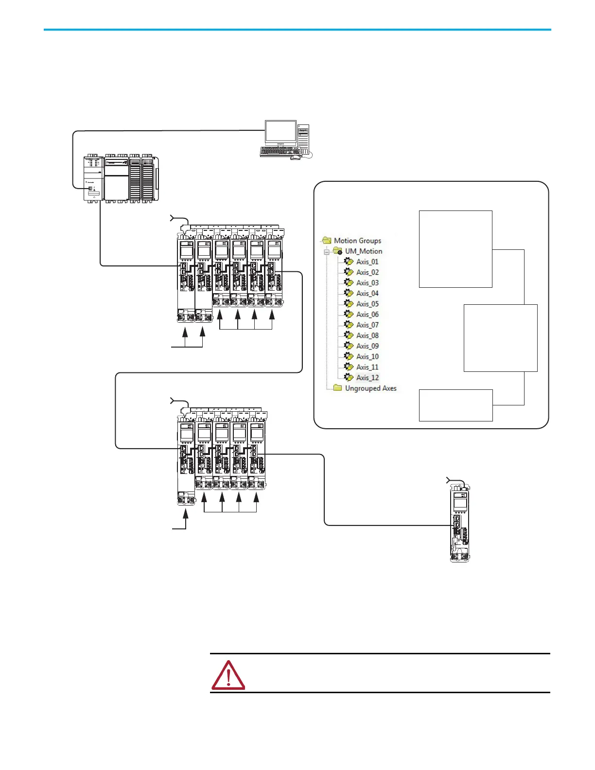
However, the 12 axes of motion are also configured as two bus-sharing groups
and one standalone drive in Module Properties > Power tab. By creating two
bus-sharing groups, a converter drive that faults in Group 1 only disables
Group 1 drives, and has no effect on the drive operation of Group 2 or the
Standalone drive.
Figure 65 - Bus-sharing Group Example
Configure Bus-sharing Groups
Group 1 is a shared AC/DC hybrid configuration. The Bus Configuration for
the first two converter drives is Shared AC/DC. The Bus Configuration for the
inverter drives is Shared DC.
Kinetix 5500 Servo Drive System
Group 1 (shared AC/DC hybrid)
Kinetix 5500 Servo Drive System
Group 2 (shared-DC common-bus)
Kinetix 5500 Servo Drive
Standalone
2198-H040-Erse
Common-bus Leader Drive
2198-H003-ERSx
Common-bus
Follower Drives
2198-H040-ERSx
Common-bus (converter)
Leader Drives
2198-H003-ERSx
Common-bus (inverter)
Follower Drives
Three-phase and
24V Input Power
Three-phase and
24V Input Power
Three-phase and
24V Input Power
CompactLogix 5370 Controller
Logix Designer
Application
1585J-M8CBJM-x
Ethernet (shielded) Cable
CompactLogix Controller Programming Network
Logix Designer Application
Bus Sharing Group 1
Axis_01
Axis_02
Axis_03
Axis_04
Axis_05
Axis_06
Bus Sharing Group 2
Axis_07
Axis_08
Axis_09
Axis_10
Axis_11
Standalone
Axis_12
1585J-M8CBJM-x
Ethernet (shielded) Cable
Controller Organizer
Module Properties>Power Tab
ATTENTION: To avoid damage to equipment, all modules that are physically
connected to the same shared-bus connection system must be part of the
same Bus Sharing Group in the Logix Designer application.

 Loading...


