64 Rockwell Automation Publication 2198-UM001M-EN-P - November 2022
Chapter 4 Connector Data and Feature Descriptions
These steps provide one method that you can use to control a brake.
1. Wire the mechanical brake according to the appropriate interconnect
diagram in Appendix A
beginning on page 179.
2. Enter the MechanicalBrakeEngageDelay and
MechanicalBrakeReleaseDelay times in the Logix Designer application.
See Axis Properties > Parameter List. The delay times must be from the
appropriate motor family brake specifications table in the Kinetix Rotary
Motion Specifications Technical Data, publication
KNX-TD001
.
3. Use the drive stop-action default setting (Current Decel & Disable).
See Axis Properties > Actions > Stop Action in the Logix Designer
application.
4. To decelerate the servo motor to 0 rpm, use the motion instruction
Motion Axis Stop (MAS).
5. To engage the brake and disable the drive, use the motion instruction
Motion Servo Off (MSF).
Control Power
The Kinetix 5500 drive requires 24V DC input power for control circuitry.
IMPORTANT Holding brakes that are available on Allen-Bradley® rotary motors are
designed to hold a motor shaft at 0 rpm for up to the rated brake-
holding torque, not to stop the rotation of the motor shaft, or be used
as a safety device.
You must command the servo drive to 0 rpm and engage the brake
only after verifying that the motor shaft is at 0 rpm.
IMPORTANT SELV and PELV rated power supplies must be used to energize external
safety devices that are connected to the Kinetix 5500 safety inputs.
The National Electrical Code and local electrical codes take precedence
over the values and methods provided. Implementation of these codes is
the responsibility of the machine builder.
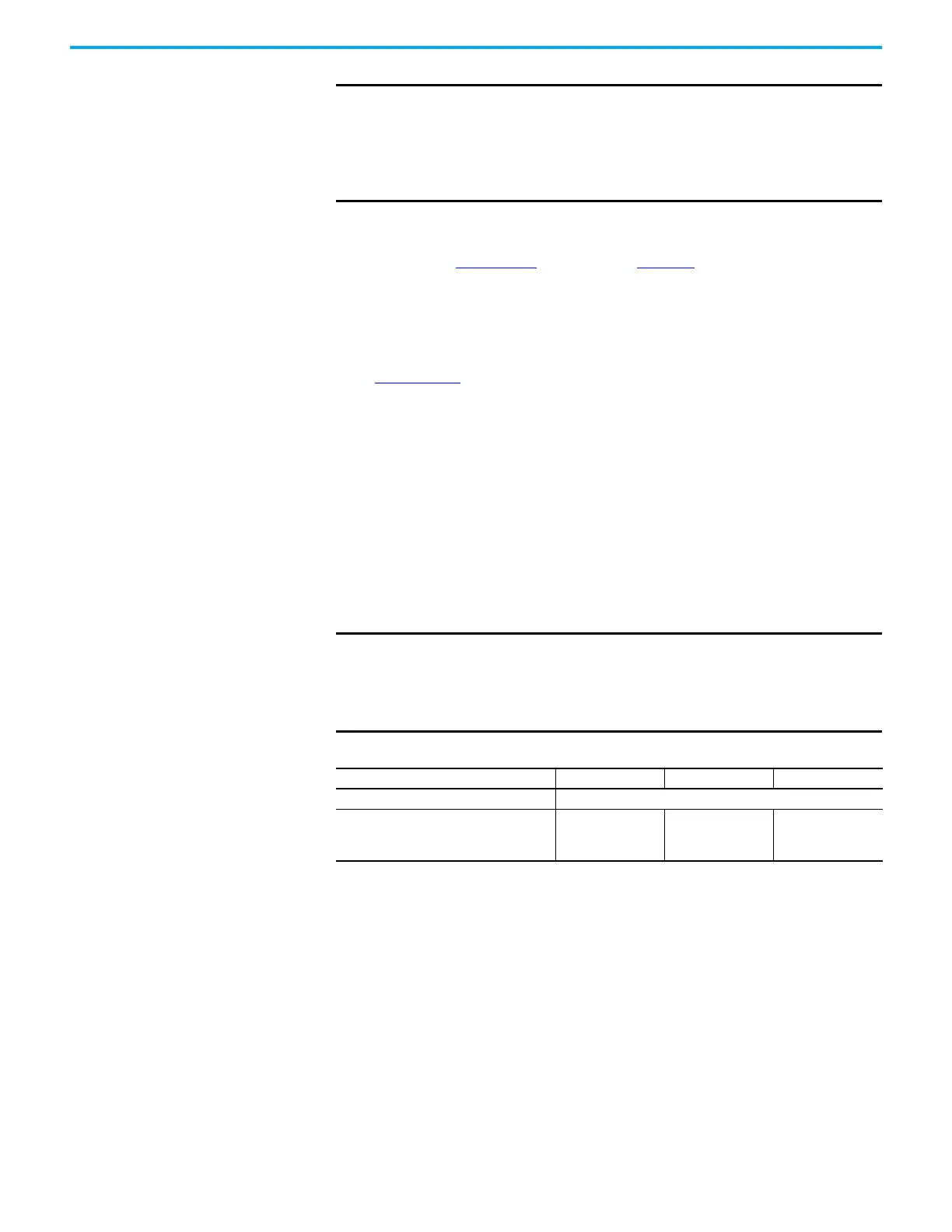
Table 32 - Control Power Input Power Specifications
Attribute Frame 1 Frame 2 Frame 3
Input voltage 21.6…26.4V DC
Control power AC input current
Nom @ 24V DC
(1)
Inrush, max
(1) Plus BC connector (MBRK+) current.
400 mA
2.0 A
800 mA
3.0 A
1.3 A
3.0 A

 Loading...


