Rockwell Automation Publication 2198-UM001M-EN-P - November 2022 83
Chapter 5 Connect the Kinetix 5500 Drive System
Motor Feedback Connections
Single motor-cable feedback connections are made by using the 2198-KITCON-
DSL feedback connector kit (included with each servo drive).
• 2090-CSxM1DF cables have flying lead conductors that are designed
specifically for Kinetix 5500 servo drives.
• 2090-CSxM1DG cables also have flying lead feedback conductors. Leads
are longer than 2090-CSxM1DF cables to accommodate Kinetix 5700
servo drives. However, because the leads are longer, extra service loops
are required with Kinetix 5500 drives.
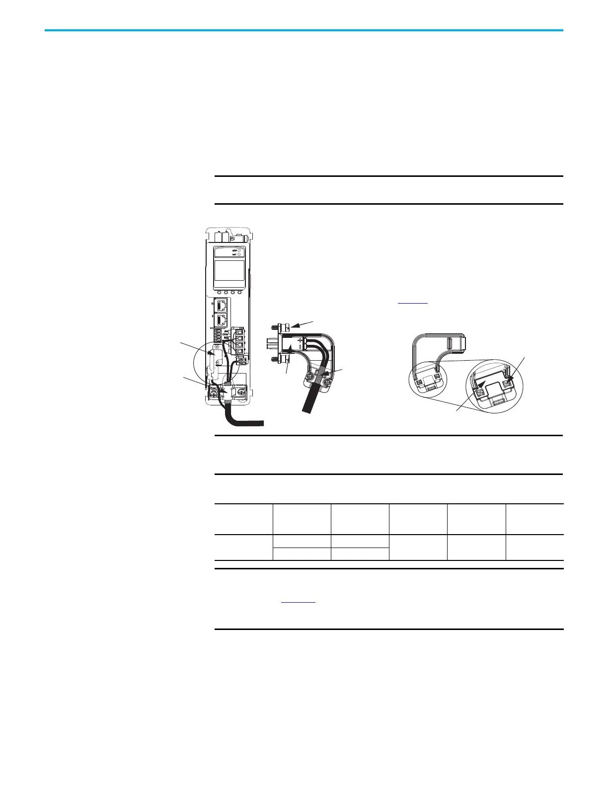
Figure 52 - MF Connector Wiring Example
IMPORTANT When using the 2198-KITCON-DSL feedback connector kit, the ambient
temperature for the Kinetix 5500 drive enclosure is 0…50 °C (32…122 °F).
Motor Cable
Shield Clamp
Motor Feedback
Connector Kit
2198-KITCON-DSL
Feedback Connector Kit
Connector
Housing
See Kinetix 5500 Feedback Connector Kit
Installation Instructions, publication
2198-IN002
, for connector kit specifications.
Internal
Grounding Plate
Cover Screws (2)
Mounting Screws (2)
Exposed Shield
Feedback Cable
(EPWR+, EPWR-)
Cover
Kinetix 5500 Servo Drive
(front view)
2090-CSBM1DF-18AAxx Motor
Cable
IMPORTANT Cable preparation and positioning that provides a high-frequency bond
between the shield braid and grounding plate is required to optimize
system performance.
Table 45 - Motor Feedback (MF) Connector Specifications
Drive Cat. No. Pin
Signal/
Wire Color
Wire Size
AWG
Strip Length
mm (in.)
Cover Screw
Torque Value
N•m (lb•in)
2198-Hxxx-ERSx
MF-1 D+/Blue
22 10.0 (0.39) 0.4 (3.5)
MF-2 D-/White/Blue
IMPORTANT The feedback bundle in 2090-CSxM1DF-18Axxx motor cables (typically
used with frame 1 drives) route around the shield clamp (as shown in
Figure 52
). The feedback bundle in2090-CSxM1DG-18, 2090-CSxM1xx-14,
and 2090-CSBM1xx-10 motor cables (typically used with frame 2 and 3
drives) route with the power and brake wires inside the cable shield.

 Loading...


