Rockwell Automation Publication 2198-UM001M-EN-P - November 2022 147
Chapter 7 Troubleshoot the Kinetix 5500 Drive System
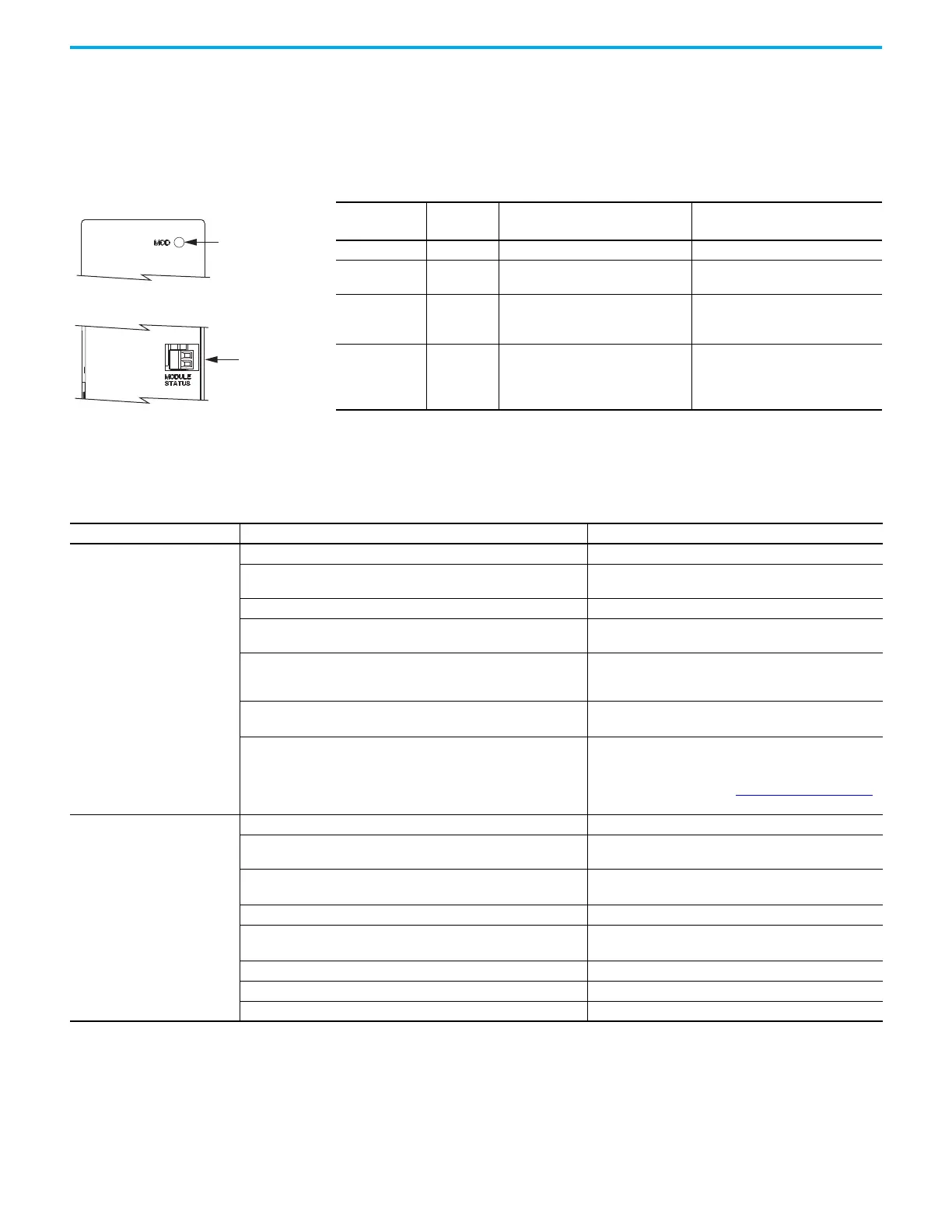
Kinetix 5500 Capacitor Module Status Indicators
The capacitor module status indicator and module status (MS) connector are
on the front of the module. The module status connector is a relay output
suitable for wiring to the Logix 5000 controller.
General Troubleshooting These conditions do not always result in a fault code, but can require
troubleshooting to improve performance.
Table 65 - Module Status Indicator and Relay Output
Module Status
Indicator
Relay
Output
(1)
(1) Wiring the module status relay output to the Logix 5000 controller is optional.
Status Resolution
Steady Green Closed Bus is fully charged and no faults exist. —
Flashing Green Open
Control power is present and the bus is
waiting to charge up.
—
Flashing Red Open
Recoverable fault
(precharge or overvoltage fault).
• Cycle control and bus power
• Verify that AC input meets
specifications
Steady Red Open
Internal, nonrecoverable fault condition
inside the module.
• Cycle control and bus power
• Verify that AC input meets
specifications
• Replace the module if fault persists
Module Status
Indicator
Kinetix 5500 Capacitor Module
Module Status
(MS) Connector
Condition Potential Cause Possible Resolution
Axis or system is unstable.
The position feedback device is incorrect or open. Check wiring.
Unintentionally in Torque mode.
Check to see what primary operation mode was
programmed.
Motor tuning limits are set too high. Run Tune in the Logix Designer application.
Position loop gain or position controller accel/decel rate is improperly
set.
Run Tune in the Logix Designer application.
Improper grounding or shielding techniques are causing noise to be
transmitted into the position feedback or velocity command lines,
causing erratic axis movement.
Check wiring and ground.
Motor Select limit is incorrectly set (servo motor is not matched to axis
module).
• Check setups.
• Run Tune in the Logix Designer application.
Mechanical resonance.
• Notch filter or output filter can be required (refer to Axis
Properties dialog box, Output tab in the Logix Designer
application).
• Enable adaptive tuning. See Adaptive Tuning on page 243
for more notch filter information.
You cannot obtain the motor
acceleration/deceleration that
you want.
Torque Limit limits are set too low. Verify that torque limits are set properly.
Incorrect motor selected in configuration.
Select the correct motor and run Tune in the Logix Designer
application again.
The system inertia is excessive.
• Check motor size versus application need.
• Review servo system sizing.
The system friction torque is excessive. Check motor size versus application need.
Available current is insufficient to supply the correct accel/decel rate.
• Check motor size versus application need.
• Review servo system sizing.
Acceleration limit is incorrect. Verify limit settings and correct them, as necessary.
Velocity Limit limits are incorrect. Verify limit settings and correct them, as necessary.
The motor is operating in the field-weakening range of operation. Reduce the commanded acceleration or deceleration.

 Loading...


