136 Rockwell Automation Publication 2198-UM001M-EN-P - November 2022
Chapter 6 Configure and Start the Kinetix 5500 Drive System
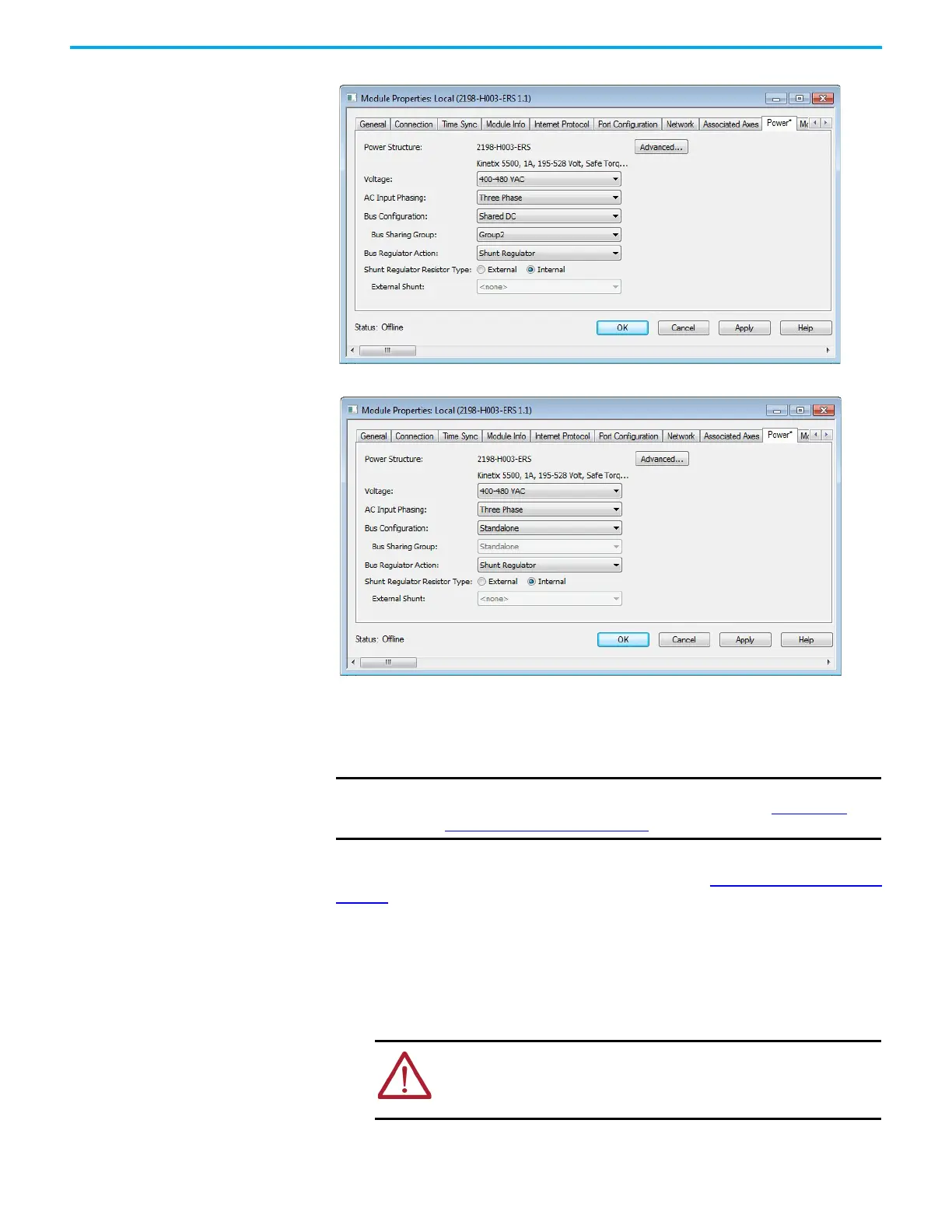
Figure 69 - Group 2 Follower Drives Configuration
Figure 70 - Standalone Drive Configuration
Test and Tune the Axes This procedure assumes that you have configured your Kinetix 5500 drive,
your Logix 5000 controller, and applied power to the system.
For help with using the Logix Designer application as it applies to testing and
tuning your axes with a Logix 5000 controller, refer to Additional Resources on
page 10.
Test the Axes
Follow these steps to test the axes.
1. Verify that the load was removed from each axis.
2. In your Motion Group folder, right-click an axis and choose Properties.
IMPORTANT Before proceeding with testing and tuning your axes, verify that the MOD
and NET status indicators are operating as described in Kinetix 5500
Drive Status Indicators on page 146.
ATTENTION: To avoid personal injury or damage to equipment, you
must remove the load from each axis as uncontrolled motion can
occur when an axis with an integral motor brake is released during
the test.

 Loading...


