Rockwell Automation Publication 2198-UM001M-EN-P - November 2022 63
Chapter 4 Connector Data and Feature Descriptions
Ethernet Communication Specifications
The PORT1 and PORT2 (RJ45) Ethernet connectors are provided for
communication with the Logix 5000® controller.
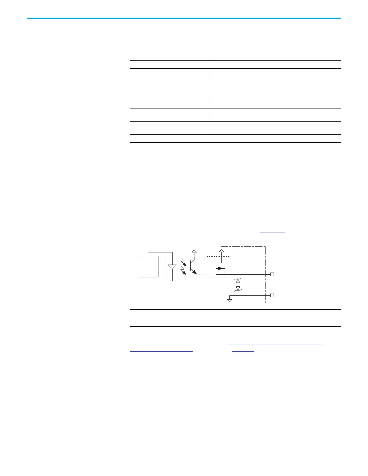
Motor Brake Circuit
The brake option is a spring-set holding brake that releases when voltage is
applied to the brake coil in the motor. The customer-supplied 24V power
supply drives the brake output through a solid-state relay. The solid-state brake
driver circuit provides the following:
• Brake current-overload protection
• Brake overvoltage protection
Two connections (BC-1 and BC-2) are required for the motor brake output.
Connections are rated for 2.0 A @ +24V (refer to Figure 35
).
Figure 35 - Motor Brake Circuit
Control of the solid-state relay to release the motor brake is configurable in the
Logix Designer application (refer to Configure SPM Motor Closed-loop
Control Axis Properties beginning on page 127). An active signal releases the
motor brake. Turn-on and turn-off delays are specified by the
MechanicalBrakeEngageDelay and MechanicalBrakeReleaseDelay settings.
Attribute Value
Communication
The drive auto-negotiates speed and duplex modes. These modes can
be forced through the Logix Designer application. 100BASE-TX, full-
duplex is recommended for maximum performance.
Cyclic update period 1.0 ms, min
Embedded switch features
Three-port, cut-through, time correction on IEEE-1588 packets, limited
filtering, quality of service with four priority levels
Auto MDI/MDIX crossover detection/
correction
Yes
Port-to-port time synchronization
variation
100 ns, max
Cabling CAT5e shielded, 100 m (328 ft) max
MBRK+ (BC-1)
MBRK– (BC-2)
24V PWR
24V COM
INT PWR
Kinetix 5500
Servo Drive
Control
Board
Inductive
Energy
Clamp
IMPORTANT Motor parking-brake switching frequency must not exceed
10 cycles/min.

 Loading...


