Rockwell Automation Publication 2198-UM001M-EN-P - November 2022 239
Appendix D Motor Control Feature Support
Phase Loss Detection The phase-loss detection feature is designed to determine if motor power
wiring is electrically connected to a motor and that reasonable current control
exists. This attribute enables the operation of the drive's torque proving
functions that work in conjunction with mechanical brake control.
When the ProvingConfiguration attribute is enabled, the drive performs a
torque prove test of the motor current while in the Starting state to prove that
current is properly flowing through each of the motor phases before releasing
the brake. If the Torque Prove test fails, the motor brake stays engaged and an
FLT-S09 Motor Phase Loss exception (fault) is generated.
Torque proving is available for all motoring configurations including closed-
loop servo control and induction motors.
For permanent magnet (PM) motors, the drive attempts to apply current to the
motor phases such that all current through the motor is flux current. However,
due to the electrical angle of the motor at the time of the MSO instruction, it
may not be possible to verify the motor phase wiring with only flux current.
Therefore, with a PM motor it is possible that the motor shaft can move slightly
during torque proving if no motor brake exists to hold the load.
Phase-loss Detection Attributes
IMPORTANT The mechanical brake must be set as soon as the drive is disabled.
When the brake is under the control of the axis state machine, this is
automatic. But, when controlled externally, failure to set the brake
when the drive is disabled can cause a free-fall condition on a
vertical application.
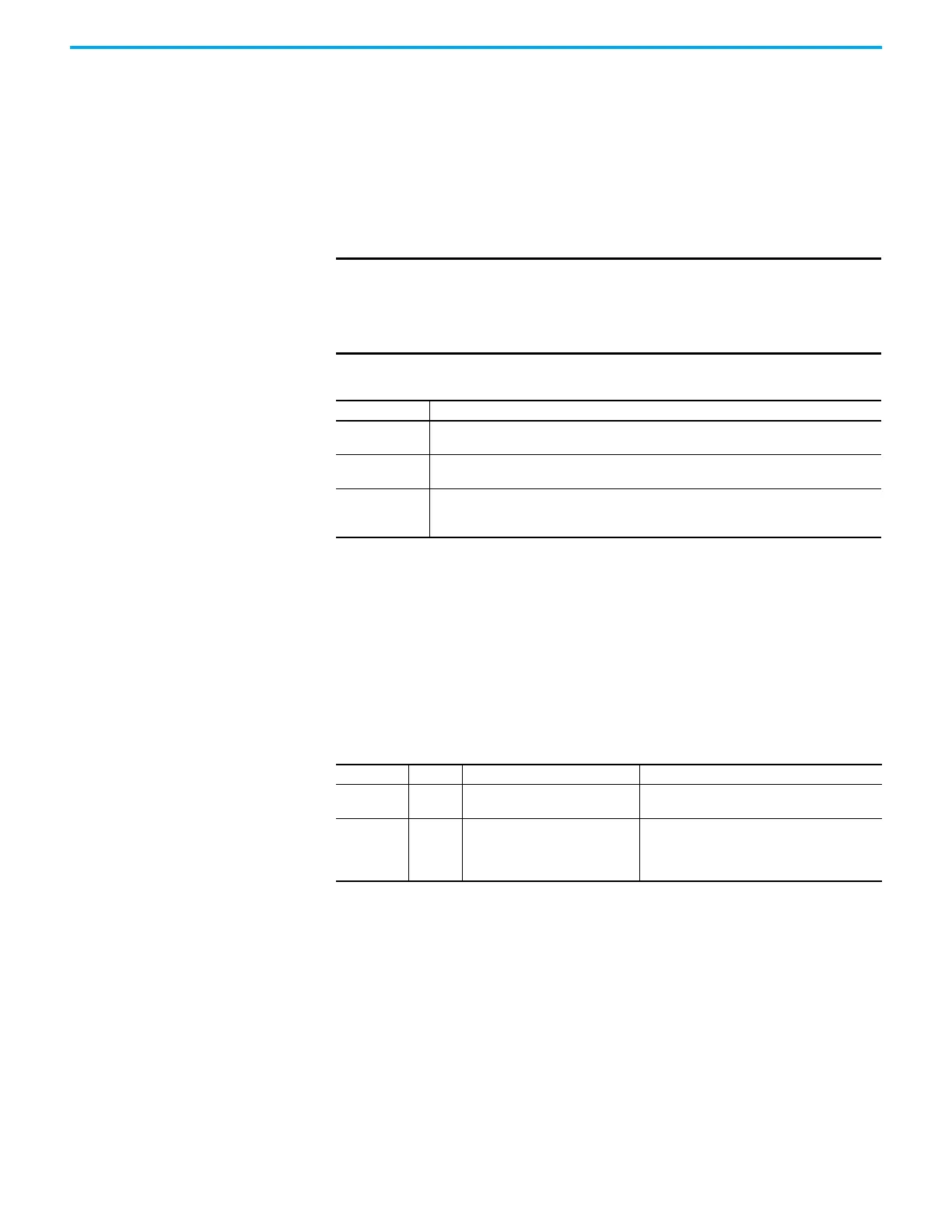
Table 99 - Phase-loss Detection Startup Sequence
Startup Phase Description
Phase 1
When the drive receives an enable request, the Starting state begins execution and torque
proving starts.
Phase 2
The torque proving feature ramps current to the motor-phase output connector and verifies
that the current feedback circuitry detects current on each of the phases.
Phase 3
Once motor-current feedback has been verified in each motor phase, the drive attempts to
enable the current control loop at a user-specified current level, and verifies that the current-
loop error tolerance is within range.
ID Access Attribute Conditional Implementation
590 SSV ProvingConfiguration
0 = Disabled
1 = Enabled
591 SSV TorqueProveCurrent
% Motor Rated
Units: Amps
Default: 0.000
Min/Max: 0/10,000

 Loading...


