Rockwell Automation Publication 2198-UM001M-EN-P - November 2022 209
Appendix C Size Multi-axis Shared-bus Configurations
Kinetix 5500 System Current Demand Example
In this example, the Kinetix 5500 drive system includes two 2198-H040-ERS
drives, four 2198-H008-ERS drives, and one capacitor module.
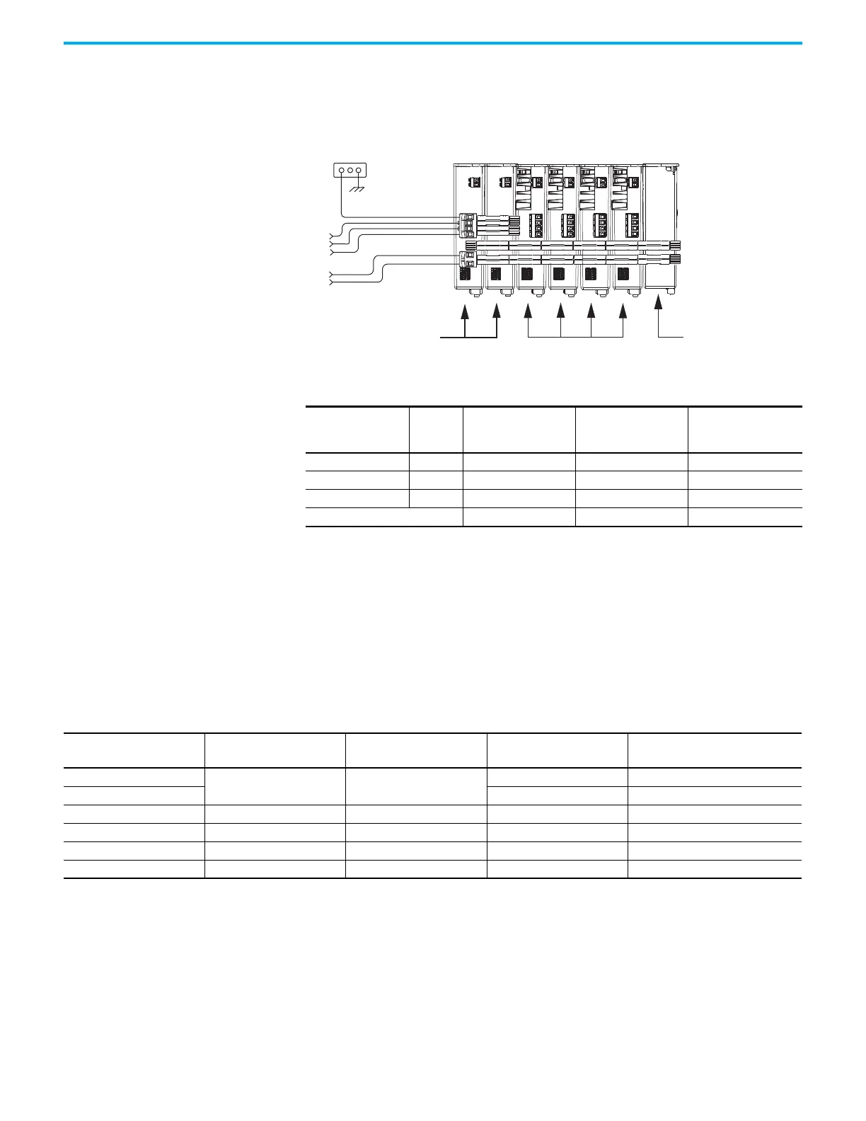
Figure 113 - Shared AC/DC Hybrid Configuration
Energy Calculations The Kinetix 5500 servo drives have internal shunt resistors for dissipating
excessive energy. In addition, Bulletin 2097 external shunt resistors and
Bulletin 2198 capacitor modules are available to increase the shared DC bus
capacitance.
Use this table to calculate the total energy absorbing potential (joules) and
determine if a capacitor module or external shunt resistor is needed.
See Motion Analyzer Online, version 7.0 or later, for custom shunt sizing.
Bonded Cabinet
Ground
Three-phase
Input Power
24V Input
Control Power
3.5 A min, non-brake motors
15.2 A min, brake motors
2198-H040-ERS
Servo Drives
2198-H008-ERS
Servo Drives
2198-CAPMOD-1300
Capacitor Module
DC Bus Connections
Table 87 - Kinetix 5500 System Current Demand Calculations
Kinetix 5500 Module
Cat. No.
Qty
24V Current
(non-brake motors)
A
DC
24V Current
(2 A brake motors)
A
DC
24V Inrush Current
(1)
A
(1) Inrush current duration is less than 30 ms.
2198-H008-ERSx 4 0.4 x 4 = 1.6 2.4 x 4 = 9.6 2 x 4 = 8
2198-H040-ERSx 2 0.8 x 2 = 1.6 2.8 x 2 = 5.6 3 x 2 = 6
2198-CAPMOD-1300 1 0.3 x 1 = 0.3 — 2 x 1 = 2
Total current demand 3.5 15.2 16
Table 88 - Energy Absorbing Potential
Kinetix 5500 Drive
Cat. No.
Internal Shunt
(1)
J
External Shunt
kJ
Capacitor Module
(1)
J
Capacitor Module, Max
(2)
J
2198-H003-ERSx
427.09 12.51
——
2198-H008-ERSx 554.4 554.4
2198-H015-ERSx 549.01 12.521 676.32 676.32
2198-H025-ERSx 575.223 12.549 702.53 957.162
2198-H040-ERSx 601.434 22.647 728.74 983.373
2198-H070-ERSx 1827.01 27.218 1954.3 2208.95
(1) Value assumes the use of one servo drive and one capacitor module.
(2) Value assumes the use of one servo drive and the maximum number of capacitor modules allowed.

 Loading...


