Rockwell Automation Publication 2198-UM001M-EN-P - November 2022 215
Appendix D Motor Control Feature Support
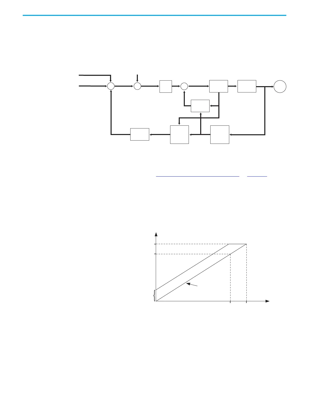
Sensorless Vector
The Sensorless Vector method uses a volts/hertz core that is enhanced by a
current resolver, slip estimator, and a voltage-boost compensator based on the
operating conditions of the motor.
Figure 117 - Sensorless Vector Method
The algorithms operate on the knowledge of the relationship between the rated
slip and torque of the motor. The drive uses applied voltages and measured
currents to estimate operating slip-frequency. You can enter values to identify
the motor resistance value or you can run a motor test to identify the motor
resistance value (see Motor Tests and Autotune Procedure
on page 228). Motor
nameplate data and test results are ways to accurately estimate the required
boost voltage.
The sensorless vector method offers better torque production and speed
regulation over a wider speed range than basic volts/hertz.
Dynamic boost is applied internally to compensate voltage drop and improve
starting torque.
Figure 118 - Approximate Load Curve
Velocity Trim
Velocity Command
Slip Speed
VHz
Motor Pole
Pairs
Vboost
Estimator
Voltage
Control
Current
Feedback
Current
Resolver
Torque
Estimate
Load
Torque
Estimator
Slip
Estimation
Inverter
Motor
Frequency,
max
Ideal, volts/hertz
Base Frequency
(nameplate)
Dynamic Boost Applied
Base Voltage
(nameplate)
Voltage, max

 Loading...


