Rockwell Automation Publication 2198-UM001M-EN-P - November 2022 37
Chapter 2 Plan the Kinetix 5500 Drive System Installation
Minimum Clearance Requirements
This section provides information to assist you in sizing your cabinet and
positioning your Kinetix 5500 drive:
• Additional clearance is required for cables and wires or the shared-bus
connection system that is connected to the top of the drive.
• Additional clearance is required if other devices are installed above and/
or below the drive and have clearance requirements of their own.
• Additional clearance left and right of the drive is required when mounted
next to noise sensitive equipment or clean wireways.
• The recommended minimum cabinet depth is 300 mm (11.81 in.).
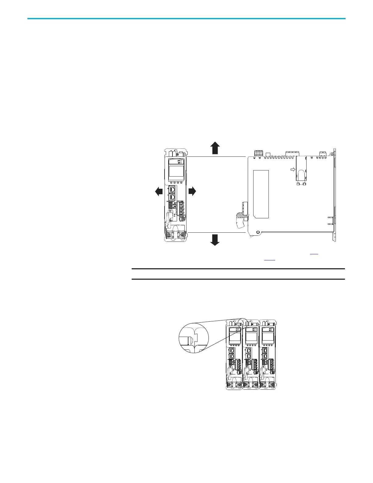
Figure 14 - Minimum Clearance Requirements
In multi-axis shared-bus configurations, drives must be spaced by aligning the
zero-stack tab and cutout.
Figure 15 - Multi-axis Shared-bus Clearance Requirements
Clearance to the right
of the drive is not
required.
Clearance to the left
of the drive is not
required.
Kinetix 5500
Servo Drive
40 mm (1.57 in.) clearance below
drive for airflow and installation.
40 mm (1.57 in.) clearance above
drive for airflow and installation.
See the Kinetix 5700, 5500, 5300, and
5100 Servo Drives Specifications
Technical Data, publication KNX-
TD003, for Kinetix 5500 drive
IMPORTANT
Mount the drive in an upright position as shown. Do not mount the drive on its side.
Zero-stack Tab and
Cutout Aligned
Shared-bus connection system for
bus-sharing configurations is not
shown for clarity.

 Loading...


