EasyManua.ls Logo

Rockwell Automation Allen-Bradley Kinetix 5500 User Manual

Rockwell Automation Allen-Bradley Kinetix 5500
260 pages
To Next Page IconTo Next Page
To Previous Page IconTo Previous Page
Page #234 background imageLoading...
Page #234 background image
234 Rockwell Automation Publication 2198-UM001M-EN-P - November 2022
Appendix D Motor Control Feature Support
SLAT Max Speed/Torque
SLAT Max Speed/Torque is a special mode of operation that is primarily used
in web handling applications. If the TorqueTrim attribute is greater than the
torque output due to the velocity regulator's control effort, then the drive
typically operates as a torque regulator. The drive can automatically enter
velocity regulation, based on conditions within the velocity regulator and the
magnitude of the velocity regulator's output relative to the torque reference.
When used for SLAT control, an application-dependent VelocityCommand
value is applied to the drive via an MAJ instruction. An application-dependent
TorqueTrim value is also applied via cyclic write. Under normal operation,
VelocityCommand is set to a level that results in the velocity regulator's control
effort becoming saturated when the motor's speed is mechanically limited. The
TorqueReference value equals the TorqueTrim value, resulting in a negative
VelocityError value.
If the mechanical speed limitation is removed (example: web break), the motor
accelerates and VelocityError becomes positive. At this time, a forced
transition to velocity regulation occurs, and the motor's speed is regulated to
the VelocityCommand attribute.
The axis remains in velocity regulation until VelocityError is less than
SLATSetPoint for a time specified by SLATTimeDelay. At this point, the axis
returns to operating as a torque regulator.
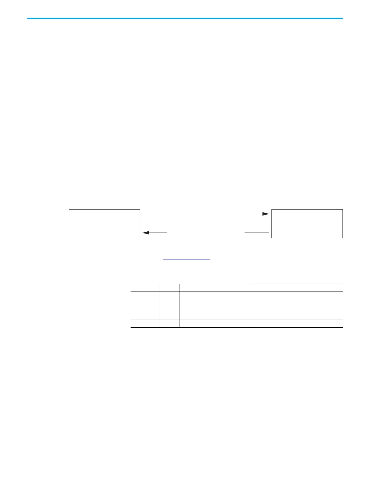
Figure 135 - SLAT Max Speed/Torque
See the Integrated Motion on the EtherNet/IP Network Reference Manual,
publication MOTION-RM003, for more information on SLAT attributes.
SLAT Attributes
Select Maximum of Velocity Loop Output
or Torque Command
(speed control is OFF)
Select Velocity Loop Output
(speed control is ON)
Velocity Error > 0
Velocity Error < SLAT Setpoint for SLAT Time
ID Access Attribute Conditional Implementation
833 Set SLAT Configuration
0 = SLAT Disable
(1)
1 = SLAT Min Speed/Torque
2 = SLAT Max Speed/Torque
(1) SLAT Disable, when viewed in version 28.00 (and earlier) of the Logix Designer application, reads Torque Only.
834 Set SLAT Set Point Velocity Units
835 Set SLAT Time Delay Seconds

Table of Contents

Other manuals for Rockwell Automation Allen-Bradley Kinetix 5500

Question and Answer IconNeed help?

Do you have a question about the Rockwell Automation Allen-Bradley Kinetix 5500 and is the answer not in the manual?

Rockwell Automation Allen-Bradley Kinetix 5500 Specifications

General IconGeneral
TypeServo Drive
Communication ProtocolEtherNet/IP
Protection RatingIP20
MountingPanel Mount
ModelKinetix 5500
Safety FeaturesSafe Torque-Off
AxisSingle Axis
Feedback TypeIncremental Encoder
Operating Temperature0°C to 55°C
Relative Humidity5…95% noncondensing

Summary

Important User Information

General Safety and Precautions

Provides critical safety warnings, attention notices, and general guidance for product operation.

Chapter 1 Start

About the Kinetix 5500 Servo Drive System

Overview of the Kinetix 5500 drive system and its capabilities.

Drive Hardware and Input Power Configurations

Details on drive hardware options and various input power configurations.

Typical Communication Configurations

Illustrates common Ethernet topologies like linear, ring, and star.

Safe Torque Off Configurations

Explains hardwired and integrated Safe Torque Off options for safety.

Chapter 2 Plan the Kinetix 5500 Drive System Installation

System Design Guidelines

Guidelines for enclosure design, panel layout, and component mounting.

AC Line Filter Selection

Guidance on selecting appropriate AC line filters for CE and UK compliance.

Circuit Breaker/Fuse Selection

Information on selecting circuit breakers and fuses for system protection.

Electrical Noise Reduction

Best practices for minimizing electrical noise and EMI interference.

Chapter 3 Mount the Kinetix 5500 Drive System

Drill-hole Patterns

Provides hole patterns for mounting drives in zero-stack or shared-bus configurations.

Mount Your Kinetix 5500 Drive

Step-by-step instructions for physically mounting the drive to the panel.

Chapter 4 Connector Data and Feature Descriptions

Kinetix 5500 Connector Data

Identifies connectors and indicators on Kinetix 5500 drive modules.

Understand Control Signal Specifications

Details on digital inputs, Ethernet communication, and power specifications.

Feedback Specifications

Information regarding Stegmann Hiperface DSL and other feedback types.

Safe Torque Off Safety Features

Explains the Safe Torque Off (STO) capability and its modes.

Chapter 5 Connect the Kinetix 5500 Drive System

Determine the Input Power Configuration

Guides users in determining the facility's input power type for the drive.

Wiring Guidelines

Provides best practices for wiring power connectors on Kinetix 5500 drives.

Wire the Power Connectors

Examples and guidelines for making connections to input power connectors.

Motor Feedback Connections

Instructions for connecting motor feedback cables using kits.

Chapter 6 Configure and Start the Kinetix 5500 Drive System

Configure the Drive

Procedures for including drives in Logix Designer and setting network parameters.

Configure the Logix 5000 Controller

Steps for configuring the Logix 5000 controller for motion applications.

Apply Power to the Kinetix 5500 Drive

Steps for applying control and mains input power to the Kinetix 5500 system.

Test and Tune the Axes

Procedures for testing axes and tuning motor performance.

Chapter 7 Troubleshoot the Kinetix 5500 Drive System

Safety Precautions

Essential safety guidelines to follow during troubleshooting.

Interpret Status Indicators

Guidance on understanding drive status indicators and fault codes.

General Troubleshooting

Common issues and potential resolutions not directly tied to fault codes.

Chapter 8 Remove and Replace Servo Drives

Before You Begin

Prerequisites and tools required for drive removal and replacement.

Remove and Replace Kinetix 5500 Servo Drives

Detailed procedures for removing and replacing servo drives.

Chapter 9 Kinetix 5500 Safe Torque Off - Hardwired Safety

Important Safety Considerations

User responsibilities for implementing hardwired safety systems.

Description of Operation

Explanation of how the Safe Torque Off (STO) feature functions.

Wire the Safe Torque Off Circuit

Guidelines for wiring the Safe Torque Off (STO) connections.

Chapter 10 Kinetix 5500 Safe Torque Off - Integrated Safety

Important Safety Considerations

User responsibilities for integrated safety applications.

Description of Operation

How the integrated STO function operates with a safety controller.

Understand Integrated Safety Drive Replacement

Procedures for replacing integrated safety drives in GuardLogix systems.

Appendix A Interconnect Diagrams

Power Wiring Examples

Wiring examples for three-phase and single-phase power connections.

Bus-sharing Wiring Examples

Wiring diagrams for shared AC, DC, AC/DC, and hybrid configurations.

System Block Diagrams

Block diagrams illustrating Kinetix 5500 drive module configurations.

Appendix B Update the Drive Firmware

Before You Begin

Lists minimum firmware and software versions required for updates.

Update Firmware

Step-by-step instructions for updating drive firmware using ControlFLASH.

Appendix C Size Multi-axis Shared-bus Configurations

Shared-bus Configurations

Information on shared AC, DC, AC/DC, and hybrid configurations.

Power-sharing Sizing Examples

Examples for sizing motors and estimating converter/inverter power.

Appendix D Motor Control Feature Support

Frequency Control Methods

Details on Basic Volts/Hertz, Fan/Pump, and Sensorless Vector methods.

Motor Category

Entering motor nameplate data for rotary induction motors.

Motor Tests and Autotune Procedure

Performing tests to identify motor parameters and tune performance.

Related product manuals